Port-based example 1, Figure 132: port-based vlan - example 1 – Allied Telesis AT-9000 Series User Manual
Page 721
AT-9000 Switch Command Line User’s Guide
693
Port-based
Example 1
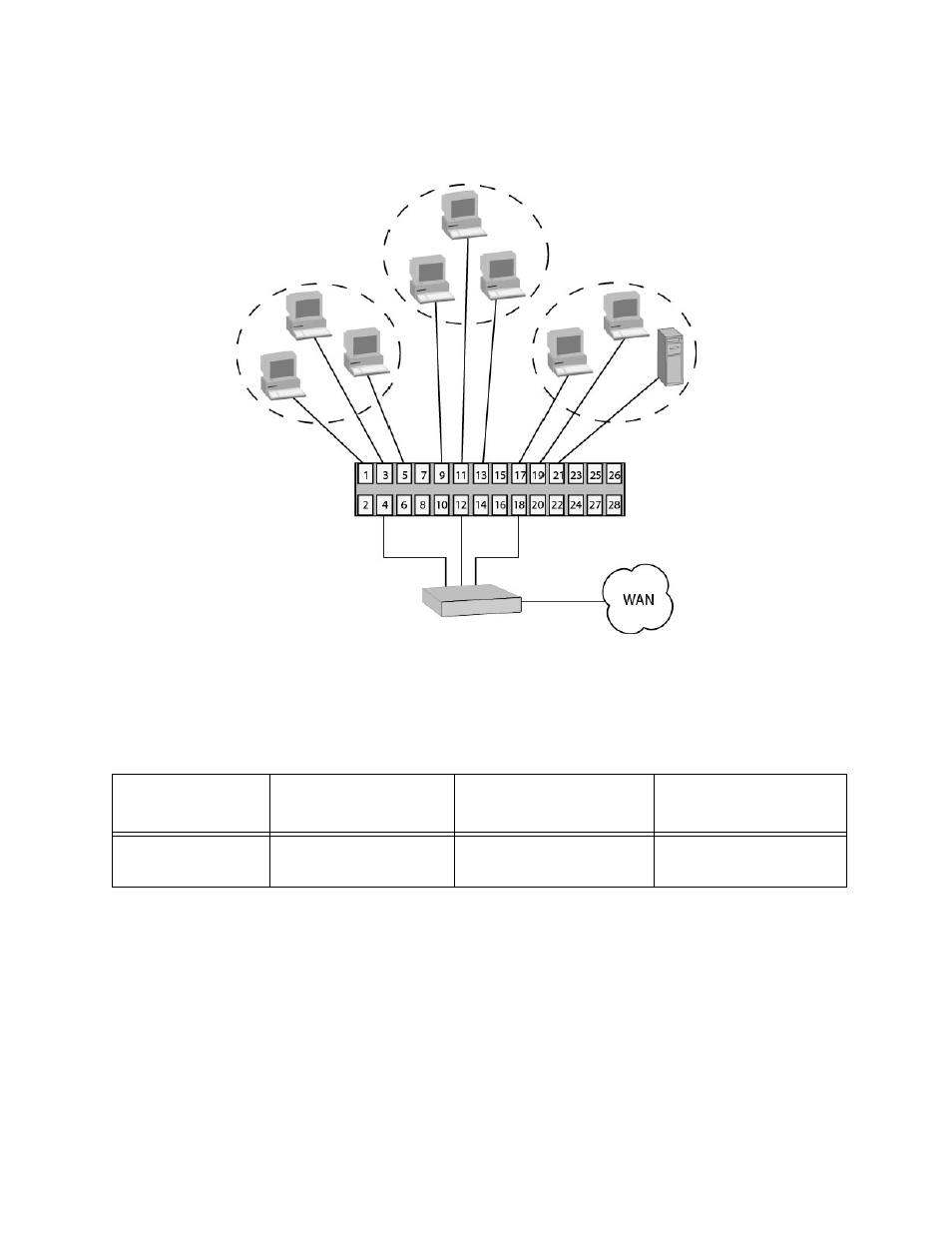
Figure 132 illustrates an example of one AT-9000 switch with three port-
based VLANs. (The Default VLAN is not shown in the following examples.)
Figure 132. Port-based VLAN - Example 1
The table below lists the port assignments for the Sales, Engineering, and
Production VLANs on the switch.
Each VLAN has a unique VID. You assign a VID number when you create
a VLAN.
The ports have been assigned PVID values. A port’s PVID is assigned
automatically by the switch when you create the VLANs. The PVID of a
port is the same as the VID in which the port is an untagged member.
In the example, each VLAN has one port connected to the router. The
router interconnects the various VLANs and functions as a gateway to the
WAN.
Router
AT-9000/28 Gigabit
Sales VLAN
(VID 2)
Engineering VLAN
(VID 3)
Production VLAN
(VID 4)
Ethernet Switch
Switch
Sales VLAN (VID 2)
Engineering VLAN
(VID 3)
Production VLAN
(VID 4)
AT-9000 Switch
Ports 1, 3 - 5
(PVID 2)
Ports 9, 11 - 13
(PVID 3)
Ports 17 - 19, 21
(PVID 4)