Brocade FastIron Ethernet Switch Platform and Layer 2 Switching Configuration Guide User Manual
Page 349
• Change a VLAN priority
• Enable or disable STP on the VLAN
1--Simple port-based VLAN configuration
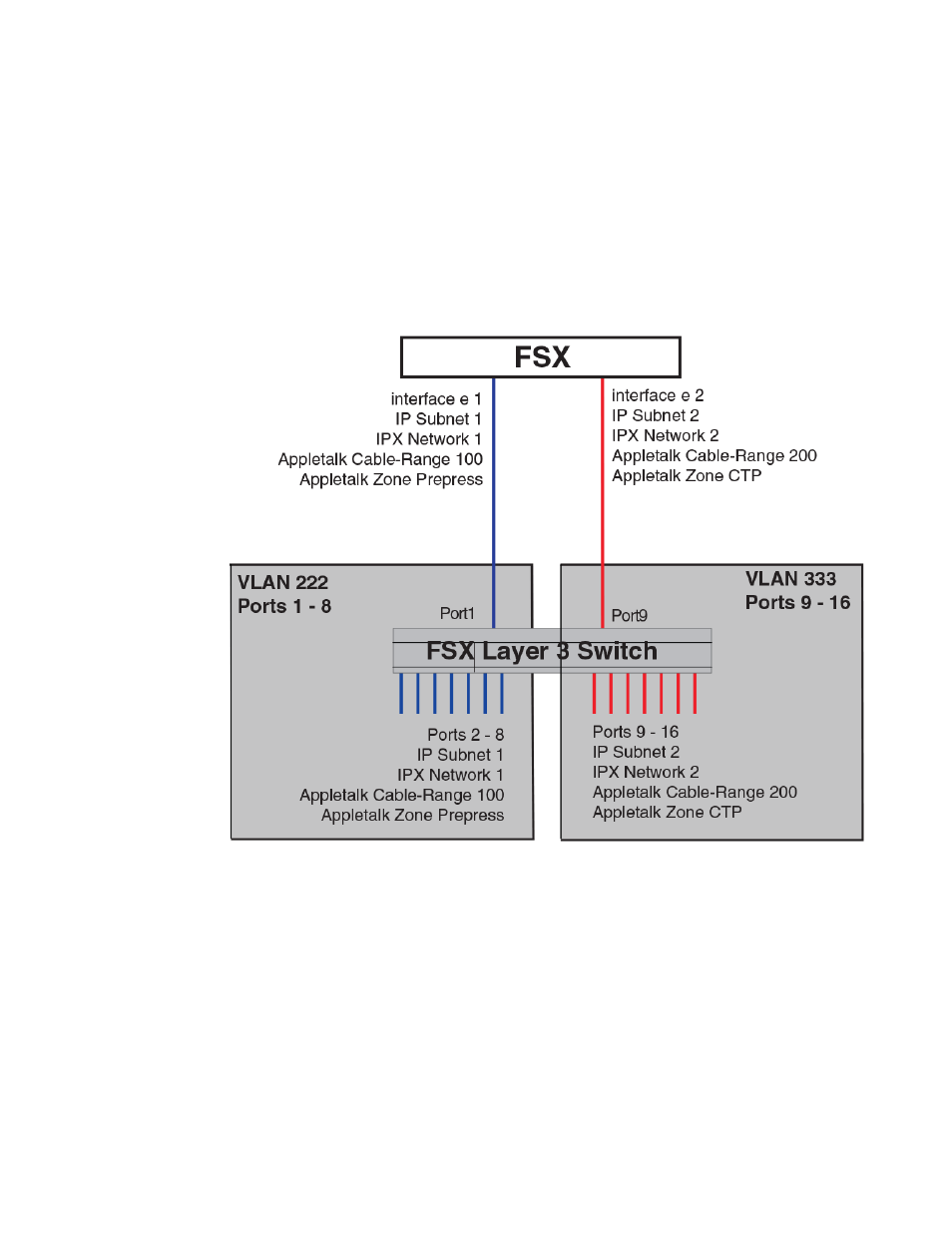
The following figure shows a simple port-based VLAN configuration using a single Brocade Layer 2
Switch. All ports within each VLAN are untagged. One untagged port within each VLAN is used to
connect the Layer 2 Switch to a Layer 3 Switch (in this example, a FSX) for Layer 3 connectivity
between the two port-based VLANs.
FIGURE 73 Port-based VLANs 222 and 333
To create the two port-based VLANs shown in the above figure, enter the following commands.
device(config)# vlan 222 by port
device(config-vlan-222)# untagged ethernet 1 to 8
device(config-vlan-222)# vlan 333 by port
device(config-vlan-333)# untagged ethernet 9 to 16
Syntax: vlan vlan-id by port
Syntax: untagged ethernet [slotnum/] portnum [to [slotnum/]portnum | ethernet [slotnum/]portnum]
2--More complex port-based VLAN configuration
The following figure shows a more complex port-based VLAN configuration using multiple Layer 2
Switches and IEEE 802.1Q VLAN tagging. The backbone link connecting the three Layer 2 Switches is
tagged. One untagged port within each port-based VLAN on FSX-A connects each separate network
wide Layer 2 broadcast domain to the router for Layer 3 forwarding between broadcast domains. The
VLANs
FastIron Ethernet Switch Platform and Layer 2 Switching Configuration Guide
349
53-1003086-04