Brocade FastIron Ethernet Switch Platform and Layer 2 Switching Configuration Guide User Manual
Page 316
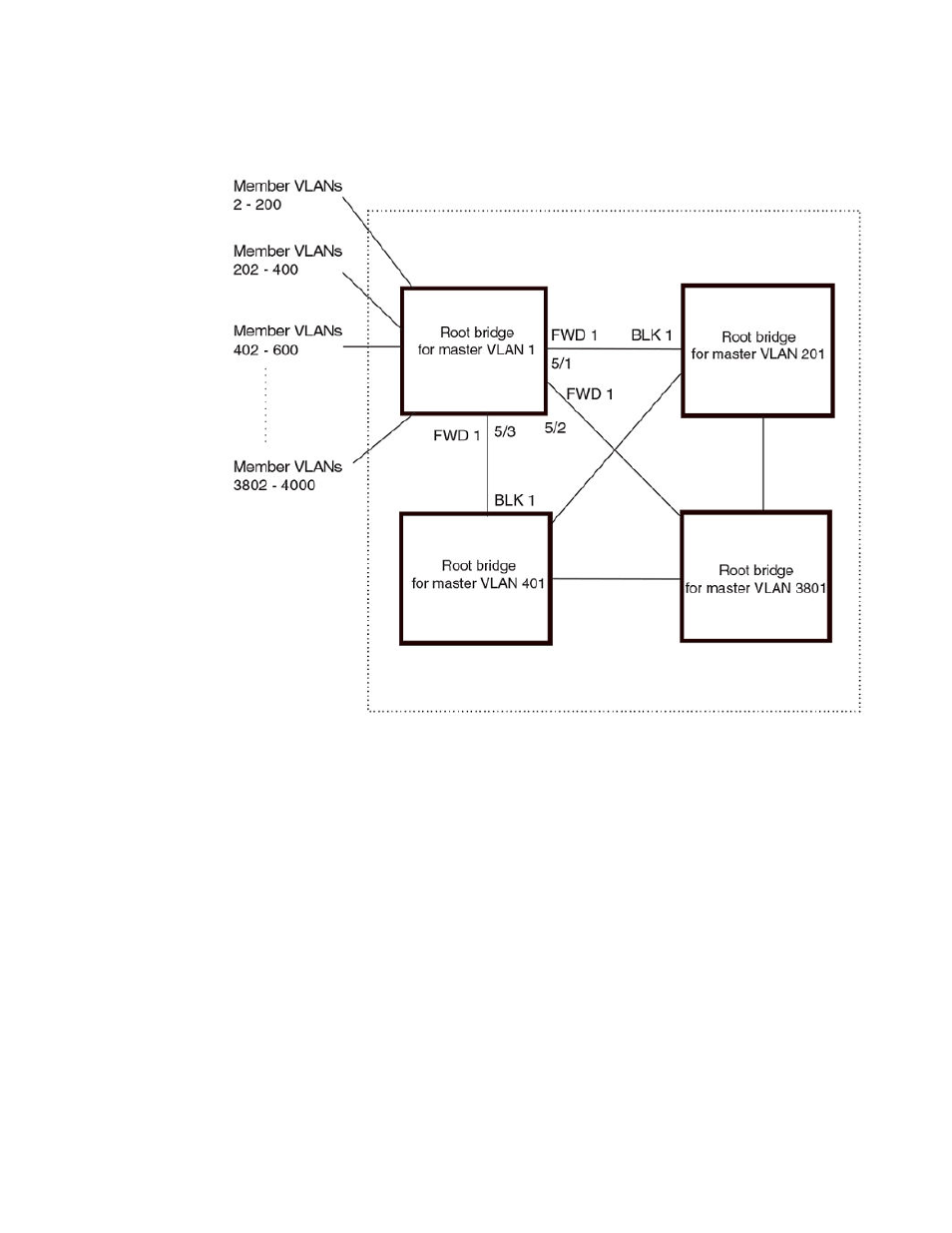
FIGURE 66 More complex STP per VLAN group example
In this example, each of the devices in the core is configured with a common set of master VLANs,
each of which contains one or more member VLANs. Each of the member VLANs in an STP group
runs the same instance of STP and uses the STP parameters configured for the master VLAN.
The STP group ID identifies the STP instance. All VLANs within an STP group run the same instance
of STP. The master VLAN specifies the bridge STP parameters for the STP group, including the
bridge priority. In this example, each of the devices in the core is configured to be the default root
bridge for a different master VLAN. This configuration ensures that each link can be used for
forwarding some traffic. For example, all the ports on the root bridge for master VLAN 1 are configured
to forward BPDUs for master VLAN spanning tree. Ports on the other devices block or forward VLAN 1
traffic based on STP convergence. All the ports on the root bridge for VLAN 2 forward VLAN 2 traffic,
and so on.
All the portss are tagged. The ports must be tagged so that they can be in both a member VLAN and
the member's master VLAN. For example, port 1/1 - and ports 5/1, 5/2, and 5/3 are in member VLAN 2
and master VLAN 1 (since master VLAN a contains member VLAN 2).
Here are the commands for configuring the root bridge for master VLAN 1 in figure
on page
314 for STP per VLAN group. The first group of commands configures the master VLANs. Notice that
the STP priority is set to a different value for each VLAN. In addition, the same VLAN has a different
STP priority on each device. This provides load balancing by making each of the devices a root bridge
for a different spanning tree.
device(config)#vlan 1
Spanning Tree Protocol
316
FastIron Ethernet Switch Platform and Layer 2 Switching Configuration Guide
53-1003086-04