How mct works – Brocade FastIron Ethernet Switch Platform and Layer 2 Switching Configuration Guide User Manual
Page 156
jitter, not only on the affected devices locally, but throughout the span topology. With MCT, member
links of the trunk are split and connected to two clustered MCT-supporting switches. MCT has
integrated loop detections, which allows all links to be active. If a failure is detected, traffic is
dynamically allocated across the remaining links. The failure detection and allocation of traffic occur in
sub-second time, without impact on the rest of the network.
MCT inherits all of the benefits of a trunk group and allows multiple physical links to act as a single
logical link. The resulting available bandwidth is an aggregate of all the links in the group. Traffic is
shared across the links in the group using dynamic flow-based load balancing, and traffic is moved to
a remaining link group in sub-seconds if a failure occurs on one of the links. MCT eliminates the single
point of failure that exists at the device level when all links of a trunk terminate on the same device
without the overhead associated with spanning tree. MCT diverts a subset of the links to a second
device to provide redundancy and sub-second fault detection at the device level.
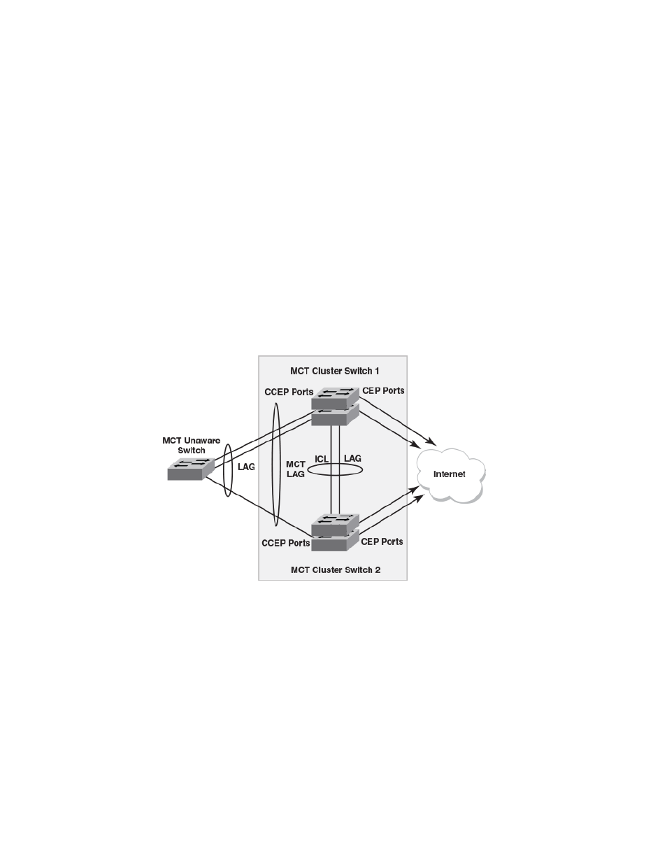
How MCT works
The following table shows a basic MCT configuration. The MCT originates at a single MCT-unaware
server or switch and terminates at two MCT-aware devices.
FIGURE 25 How MCT works
The MCT process involves the following processes:
• Sub-second failover occurs if a link, module, switch fabric, control plane, or device fails.
• Sub-second failover operates at the physical level.
• Layer 2 and Layer 3 forwarding (when using fast path forwarding) is done at the first hop regardless
of VRRP-E state.
• Load balancing is flow based (it does not involve VLANs sharing across network links).
• Resiliency is supported regardless of the traffic type (Layer 3, Layer 2, or non-IP legacy protocols).
• Interaction with Metro Ring Protocol (MRP) builds larger resilient Layer 2 domains.
• Device-level redundancy is provided in addition to link and modular redundancy.
• Traffic received from an ICL port is not forwarded to the Cluster Client Edge Ports (CCEPs) if the
MCT peer device has the ability to reach the same cluster client.
• Traffic received from non-ICL ports is forwarded the same way as non-MCT devices.
• Known unicast, multicast, and broadcast traffic received on Cluster Edge Ports (CEP) or ICL ports
is forwarded to the destination port.
How MCT works
156
FastIron Ethernet Switch Platform and Layer 2 Switching Configuration Guide
53-1003086-04