16 axis traverse limits, datum display – HEIDENHAIN TNC 426B (280 472) ISO programming User Manual
Page 347

13 MOD Functions
332
13.14 Selecting the Program Language for Manual Data Input;
13.15
Axis Selection f
or L
-Bloc
k Gener
ation (Not
TNC 41
0,
Only Con
v
ersational)
13.14 Programming Language for
MDI
The Program Input MOD function lets you switch between HEIDEN-
HAIN conversational dialog or ISO format in the MDI mode:
■
To program in conversational dialog:
Program input: HEIDENHAIN
■
To program according to ISO:
Program input: ISO
13.15 Selecting the Axes for Generating
L Blocks (not TNC 410, only
Conversational Dialog)
The axis selection input field enables you to define the current tool
position coordinates that are transferred to an L block. To generate a
separate L block, press the ACTUAL-POSITION-CAPTURE soft key.
The axes are selected by bit-oriented definition similar to
programming the machine parameters:
Axis selection
%11111
Transfer the X, Y, Z, IV and
V axes
Axis selection
%01111
Transfer the X, Y, Z, IV
axes
Axis selection
%00111
Transfer the X, Y and Z
axes
Axis selection
%00011
Transfer the X and Y
Axis selection
%00001
Transfer the X axis
13.16 Axis Traverse Limits, Datum
Display
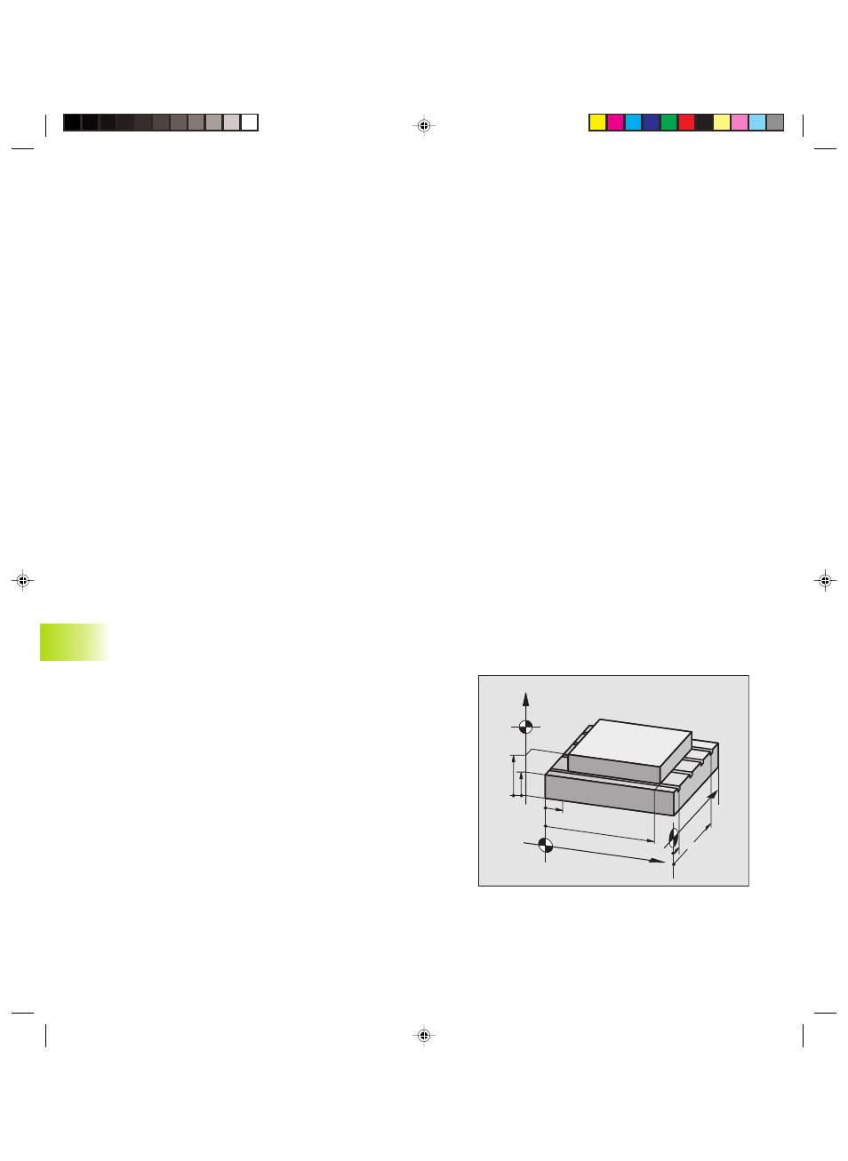
The AXIS LIMIT mod function allows you to set limits to axis
traverse within the machine’s actual working envelope.
Possible application:
to protect an indexing fixture against tool collision.
The maximum range of traverse of the machine tool is defined by
software limit switches. This range can be additionally limited
through the AXIS LIMIT mod function. With this function, you can
enter the maximum and minimum traverse positions for each axis,
referenced to the machine datum. If several traverse ranges are
possible on your machine, you can set the limits for each range
separately using the soft keys LIMIT SWITCH (1) to LIMIT SWITCH
(3) (not TNC 410).
Z
Y
X
Z
min
Z
max
X
min
Y
max
Y
min
X
max
Pkap13.pm6
29.06.2006, 08:07
332
