2 cabinet-mounting switch, 13 cable management, 1 correct labels – H3C Technologies H3C S9500 Series Switches User Manual
Page 98: 2 cable management requirements, 2 cabinet-mounting switch -29, 13 cable management -29, 1 correct labels -29, 2 cable management requirements -29, 2 cabin, Et-mounting switch
Installation Manual
H3C S9500 Series Routing Switches
Chapter 4 Switch Installation
4-29
cabling channel), and the chassis power cords (AC/DC power cords) are
routed in the front of the chassis.
4.12.2 Cabin
If t
cab
hassis and are routed up or
down to pass through the chassis top or the raised floor depending on the available
quipment room condition (that is, the signal cables are routed into the chassis either
4.13 Cable Management
d fill in the labels for them correctly and stick them
etails, refer to the description of label usage in
Appendix A Engineering Labels for Cables.
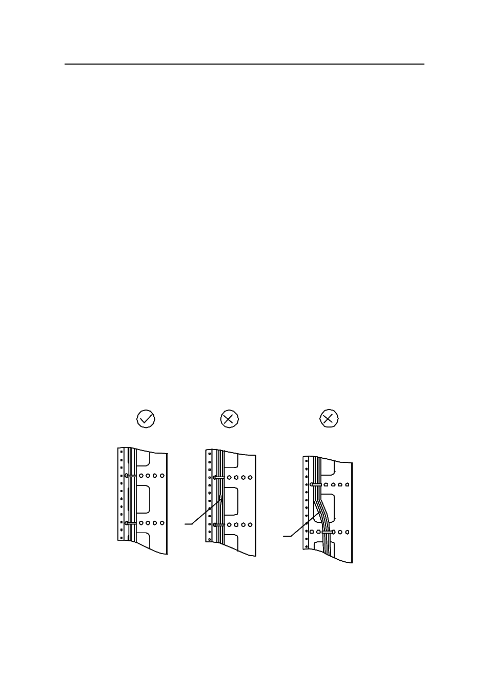
4.13.2 Cable Management Requirements
Bundle and put the cables inside the cabinet in a straight and neat way. No
(along the
et-Mounting Switch
he switch is mounted in a 19-inch standard cabinet or B68-22 cabinet, the LPU
les are bound on the cabling rack at the left side of the c
e
from the cabling rack on the chassis top or from the cabling trough under the floor) of
the exchange office. The power cords run along the left-front of the chassis and out of
the chassis either from the top or the raised floor depending on the equipment room
conditions (DC power distribution cabinet, lightning protection box, and terminal block,
etc.) of the exchange office.
4.13.1 Correct Labels
Before bundling the cables, you shoul
to the right position on the cables. For d
z
intertwinement or bending is allowed.
Intertwined
Bent
Intertwined
Bent
Figure 4-31 Cable bundling example I
- H3C S7500E Series Switches H3C S7500 Series Switches H3C S5800 Series Switches H3C S5820X Series Switches H3C S5500 Series Switches H3C S5120 Series Switches H3C S3610[S5510] Series Switches H3C S3600 Series Switches H3C S3100 Series Switches OAA For Routers H3C WX6000 Series Access Controllers H3C WX5000 Series Access Controllers H3C WX3000 Series Unified Switches H3C LSQM1WCMB0 Access Controller Module H3C LSBM1WCM2A0 Access Controller Module H3C WA2600 Series WLAN Access Points H3C WA2200 Series WLAN Access Points H3C SecPath F1000-E H3C SecPath F1000-A H3C SecPath F1000-S H3C SecPath F100-A H3C SecPath F100-C-EI H3C SecPath V100-E H3C SecCenter iTAS H3C Device Manager