Figure b-4 and, On. figure b-4 shows the inst – H3C Technologies H3C S9500 Series Switches User Manual
Page 155
Installation Manual
H3C S9500 Series Routing Switches
Appendix B Installation of B68 Cabinet
B-4
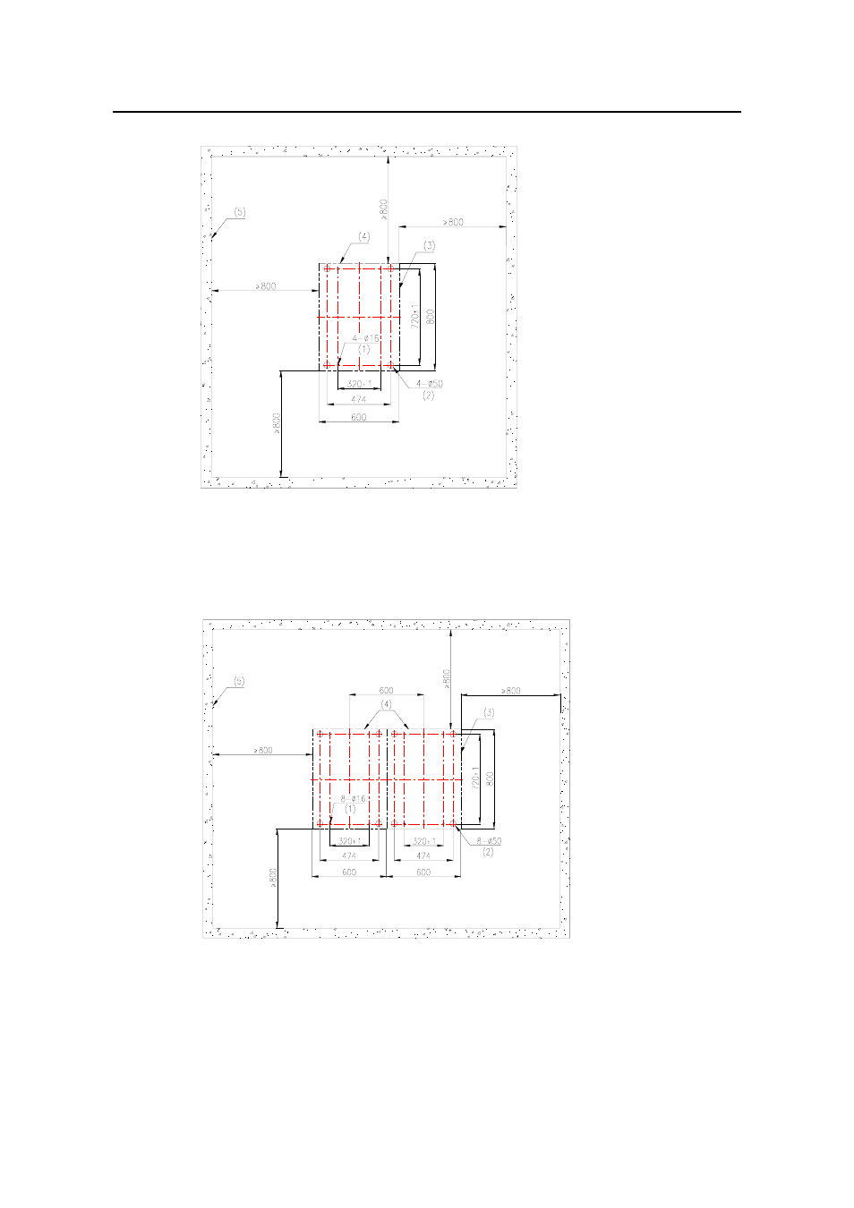
(1) M12 expansion bolt hole mark
(2) Cabinet foot location mark
(3) Cabinet outline
(4) Rear of cabinet
(5) Wall or reference body
Figure B-4
Installation holes and cabinet foot location marks of a single cabinet
(1) M12 expansion bolt hole mark
(2) Cabinet foot location mark
(3) Cabinet outline
(4) Rear of cabinet
(5) Wall or reference body
Figure B-5
Installation holes and cabinet foot location marks of two cabinets
This manual is related to the following products:
- H3C S7500E Series Switches H3C S7500 Series Switches H3C S5800 Series Switches H3C S5820X Series Switches H3C S5500 Series Switches H3C S5120 Series Switches H3C S3610[S5510] Series Switches H3C S3600 Series Switches H3C S3100 Series Switches OAA For Routers H3C WX6000 Series Access Controllers H3C WX5000 Series Access Controllers H3C WX3000 Series Unified Switches H3C LSQM1WCMB0 Access Controller Module H3C LSBM1WCM2A0 Access Controller Module H3C WA2600 Series WLAN Access Points H3C WA2200 Series WLAN Access Points H3C SecPath F1000-E H3C SecPath F1000-A H3C SecPath F1000-S H3C SecPath F100-A H3C SecPath F100-C-EI H3C SecPath V100-E H3C SecCenter iTAS H3C Device Manager