2 panel and leds, 3 matching cable, 2 panel and leds -13 – H3C Technologies H3C S9500 Series Switches User Manual
Page 54: 3 matching cable -13
Installation Manual
H3C S9500 Series Routing Switches
Chapter 2 LPU Modules
2-13
2.9.2 Panel and LEDs
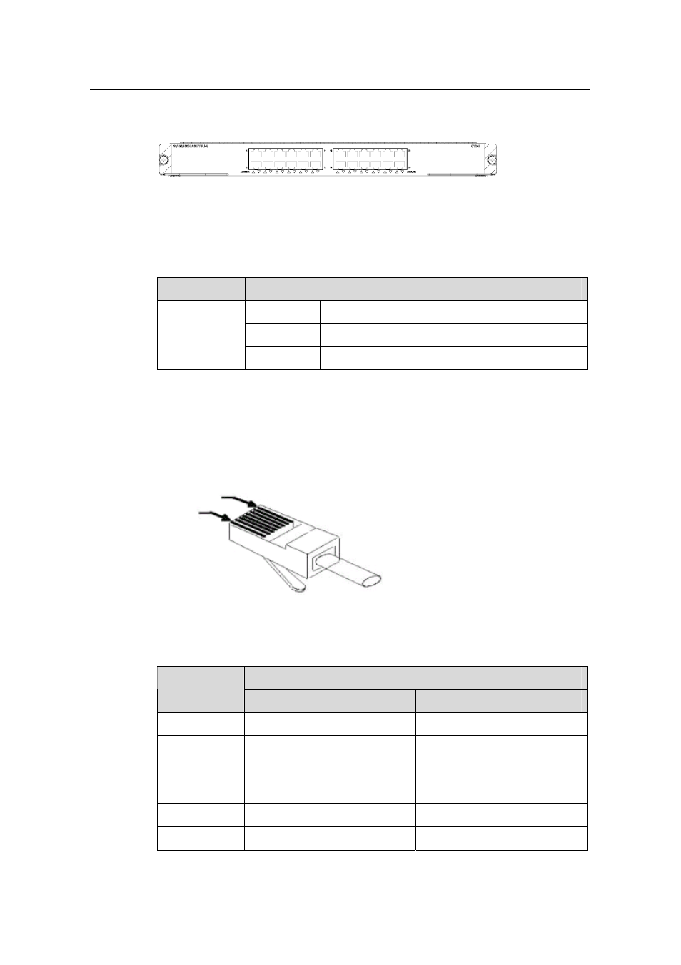
Figure 2-9 GT24 module panel
The GT24 module has one LEDs for each port on its panel.
Table 2-23 Port LEDs on the GT24 module
LED
Status
ON
No link is present.
OFF
A link is present.
LINK/ACT
Blinking
Packets are being transmitted/received on the port.
2.9.3 Matching Cable
The ports on the GT24 module uses RJ-45 connectors (see Table 2-24) and category-5
twisted pair cables which allow the transmission distance of 100 m (328 ft).
PIN #8
PIN #1
Figure 2-10 RJ-45 connector
Table 2-24 Pin assignment of the RJ-45 GE connector
10Base-T/100Base-T/1000Base-TX
Pin No.
Signal
Function
1
MX_0+
Transmit and receive data.
2
MX_0-
Transmit and receive data.
3
MX_1+
Transmit and receive data.
4
MX_2+
Transmit and receive data.
5
MX_2-
Transmit and receive data.
6
MX_1-
Transmit and receive data.
- H3C S7500E Series Switches H3C S7500 Series Switches H3C S5800 Series Switches H3C S5820X Series Switches H3C S5500 Series Switches H3C S5120 Series Switches H3C S3610[S5510] Series Switches H3C S3600 Series Switches H3C S3100 Series Switches OAA For Routers H3C WX6000 Series Access Controllers H3C WX5000 Series Access Controllers H3C WX3000 Series Unified Switches H3C LSQM1WCMB0 Access Controller Module H3C LSBM1WCM2A0 Access Controller Module H3C WA2600 Series WLAN Access Points H3C WA2200 Series WLAN Access Points H3C SecPath F1000-E H3C SecPath F1000-A H3C SecPath F1000-S H3C SecPath F100-A H3C SecPath F100-C-EI H3C SecPath V100-E H3C SecCenter iTAS H3C Device Manager