Ii. connecting poe power cable, 6 installing the ac power distribution box, 1 terminal block – H3C Technologies H3C S9500 Series Switches User Manual
Page 85: 6 installing the ac power distribution box -16, 1 terminal block -16, 6 inst lling the ac power distribution box
Installation Manual
H3C S9500 Series Routing Switches
Chapter 4 Switch Installation
4-16
II.
e with a cross screwdriver.
rd to the NEG (-) terminal of the
w; insert the other end to the NEG (-)
r cord to the RTN (
+) terminal of the
w; insert the other end to the NEG (-)
Figure 4-16 Ground PoE chassis
Connecting PoE power cable
Loosen the mounting screw of the PoE entry modul
Insert the -48V OT terminal (blue) of the DC power co
PoE entry module and fasten the mounting scre
terminal of the external PoE power supply.
Insert the GND OT terminal (black) of the DC powe
PoE entry module and fasten the mounting scre
terminal of the external power supply.
Caution:
z
Observe the signs on devices and connect the cables correctly.
z
Choose right cables based on the load.
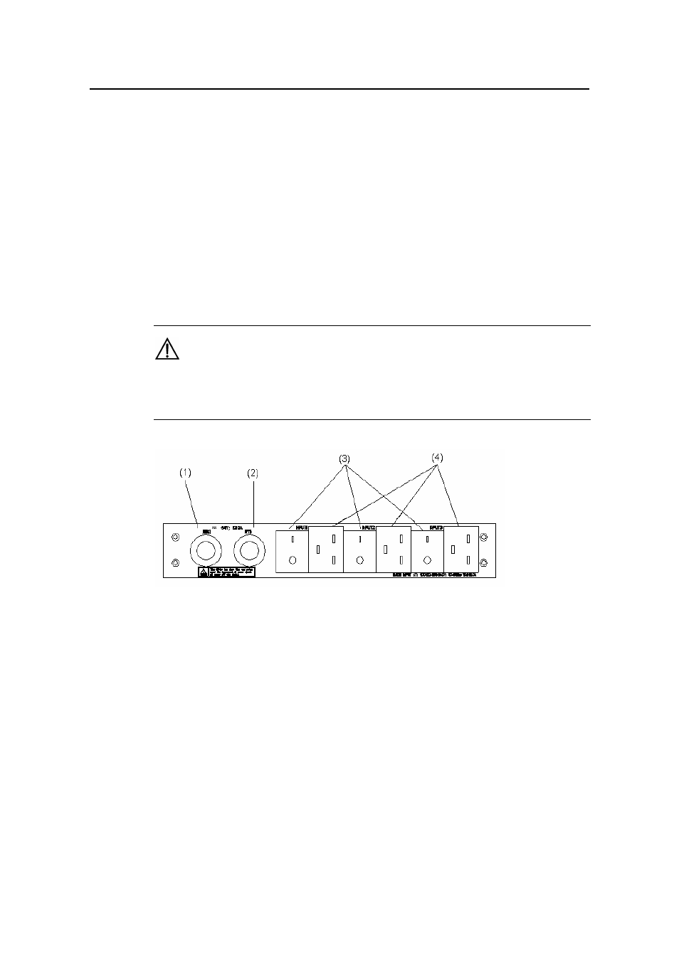
(1) DC output terminal: NEG(-)
(2) DC output terminal: RTN(+)
3
er supply
4.6 Inst lling the AC Power Distribution Box
( ) AC input switch
(4) AC input socket
Figure 4-17 Front panel of external PoE pow
a
4.6.1 Terminal Block
The terminal block is set on the bottom of a power distribution box.
- H3C S7500E Series Switches H3C S7500 Series Switches H3C S5800 Series Switches H3C S5820X Series Switches H3C S5500 Series Switches H3C S5120 Series Switches H3C S3610[S5510] Series Switches H3C S3600 Series Switches H3C S3100 Series Switches OAA For Routers H3C WX6000 Series Access Controllers H3C WX5000 Series Access Controllers H3C WX3000 Series Unified Switches H3C LSQM1WCMB0 Access Controller Module H3C LSBM1WCM2A0 Access Controller Module H3C WA2600 Series WLAN Access Points H3C WA2200 Series WLAN Access Points H3C SecPath F1000-E H3C SecPath F1000-A H3C SecPath F1000-S H3C SecPath F100-A H3C SecPath F100-C-EI H3C SecPath V100-E H3C SecCenter iTAS H3C Device Manager