3 connecting dc power cord, 3 connecting dc power cord -13 – H3C Technologies H3C S9500 Series Switches User Manual
Page 82
Installation Manual
H3C S9500 Series Routing Switches
Chapter 4 Switch Installation
4-13
4.5.3 Connecting DC Power Cord
Caution:
Power OFF all the related parts of the switch before connecting the DC power cord.
In the connection of DC power cord, a connector bar will be used, and the power cord
will be tightened into the bar using screws for the sake of reliability.
onnect DC power cord for the S9502:
(with a blue wire) of the DC power cord
sert the peer end of the OT terminal into the “-48V” connector on the
peer end of the OT terminal into the “RTN” connector on the
Insert the peer end of the OT terminal to the ground bar for the
switch.
C
Step 1: Loosen the mounting nuts of the connectors on the DC PSU using the M6
socket wrench.
Step 2: Insert the -48V OT terminal
accompanied with the switch into the “-48V” connector on the PSU and fasten the
mounting nut. In
external power supply.
Step 3: Insert one end of the GND OT terminal (with a black wire) of the DC power cord
accompanied with the switch into the “RTN” connector on the PSU and fasten the
mounting nut. Insert the
external power supply.
Step 4: Insert one end of the PGND OT terminal (with a yellow-green wire) of the DC
power cord accompanied with the switch into the “PGND” connector on the PSU and
fasten the mounting nut.
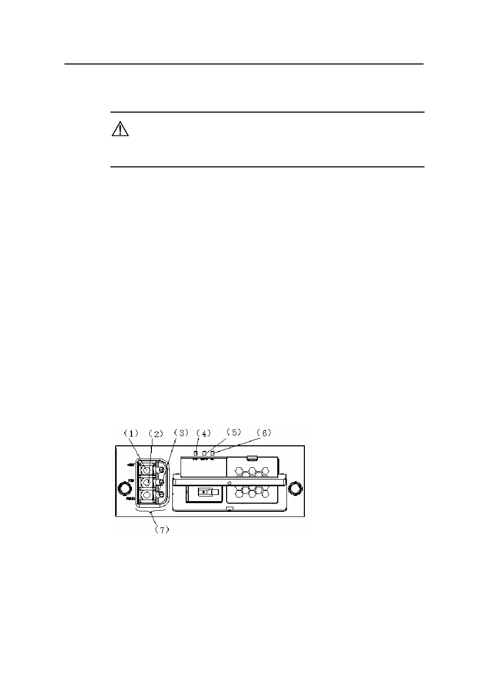
(1) -48V
(2) RTN
(3) PGND
(4) Input LED
(5) Output LED
(6) Fail LED
(7) Connector block
Figure 4-13 Connect DC power cord for the S9502
C
power cord for the S9505/S
switches.
onnect the DC
9508/S9512
- H3C S7500E Series Switches H3C S7500 Series Switches H3C S5800 Series Switches H3C S5820X Series Switches H3C S5500 Series Switches H3C S5120 Series Switches H3C S3610[S5510] Series Switches H3C S3600 Series Switches H3C S3100 Series Switches OAA For Routers H3C WX6000 Series Access Controllers H3C WX5000 Series Access Controllers H3C WX3000 Series Unified Switches H3C LSQM1WCMB0 Access Controller Module H3C LSBM1WCM2A0 Access Controller Module H3C WA2600 Series WLAN Access Points H3C WA2200 Series WLAN Access Points H3C SecPath F1000-E H3C SecPath F1000-A H3C SecPath F1000-S H3C SecPath F100-A H3C SecPath F100-C-EI H3C SecPath V100-E H3C SecCenter iTAS H3C Device Manager