B.2.1 introduction to anchor plate – H3C Technologies H3C S9500 Series Switches User Manual
Page 153
Installation Manual
H3C S9500 Series Routing Switches
Appendix B Installation of B68 Cabinet
B-2
Caution:
The feet are insulated. The anchor plate components include insulating units. During
construction, make sure that the insulating units are correctly installed so that the whole
set of equipment is insulated from the ground before the ground wire is connected, thus
effectively meeting the insulation requirement.
B.2.1 Introduction to Anchor Plate
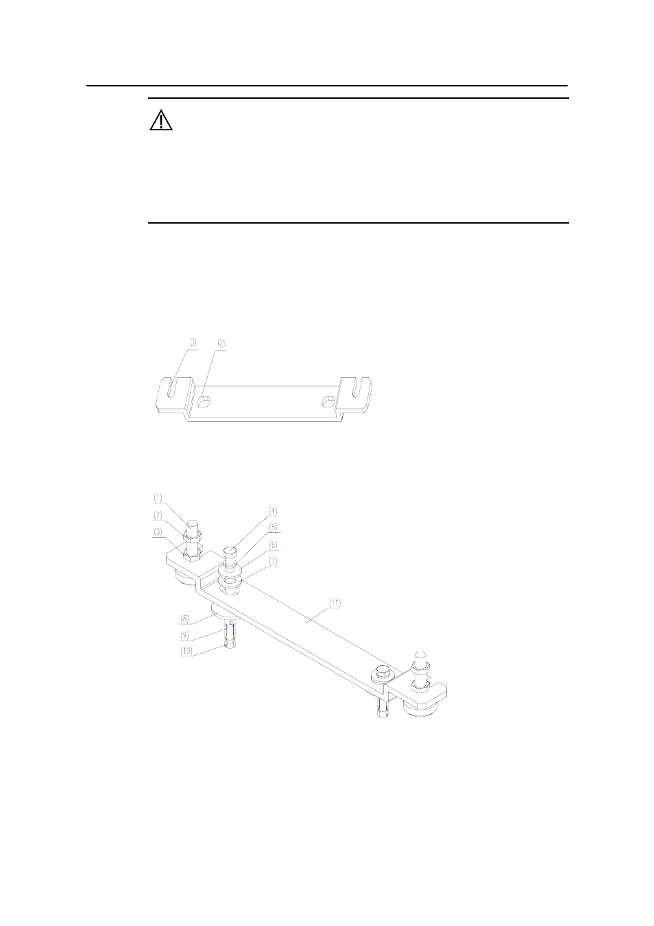
The anchor plate of the B68-22 cabinet is shown in Figure B-1, and the installations of
the anchor plate and cabinet feet are shown in Figure B-2.
(1) Cabinet foot fixing connection trough
(2) Anchor plate fixing connection hole
Figure B-1
Anchor plate of the B68-22 cabinet
(1) Cabinet foot
(2) Retaining nut of the cabinet
(3) Retaining nut of anchor plate
(4) Bolt M12
×70
(5) Spring washer Φ12
(6) Big flat washer Φ12
(7) Insulating covering
(8) Insulating washer of anchor plate
(9) Expansion tube
(10) Expansion nut
(11) Anchor plate of the B68-22 cabinet
Figure B-2
Composition of Anchor plate of the B68-22 cabinet
- H3C S7500E Series Switches H3C S7500 Series Switches H3C S5800 Series Switches H3C S5820X Series Switches H3C S5500 Series Switches H3C S5120 Series Switches H3C S3610[S5510] Series Switches H3C S3600 Series Switches H3C S3100 Series Switches OAA For Routers H3C WX6000 Series Access Controllers H3C WX5000 Series Access Controllers H3C WX3000 Series Unified Switches H3C LSQM1WCMB0 Access Controller Module H3C LSBM1WCM2A0 Access Controller Module H3C WA2600 Series WLAN Access Points H3C WA2200 Series WLAN Access Points H3C SecPath F1000-E H3C SecPath F1000-A H3C SecPath F1000-S H3C SecPath F100-A H3C SecPath F100-C-EI H3C SecPath V100-E H3C SecCenter iTAS H3C Device Manager