14 verifying the installation, 14 verifying the installation -32, Ing the installation 4.14 verify – H3C Technologies H3C S9500 Series Switches User Manual
Page 101
Installation Manual
H3C S9500 Series Routing Switches
Chapter 4 Switch Installation
4-32
direction should be bundled
ng with cable ties.
z
The power cords of the same type and in the same
together and kept neatly and straight;
The following table lists the requirements in the bundli
Table 4-3 Tie-binding parameters
Cable bundle diameter (mm)
Space between bundles (mm)
10
80 to 150
10 to 30
150 to 200
30
200 to 300
z
No cable or bundle can tie a knot;
z
The metal parts of the crimped cold-pressed terminal blocks (such as air switch)
cannot stretch beyond the blocks.
ing the Installation
4.14 Verify
Caution:
Con
he power before checking, otherwise, improper
n
firm that you have turned off t
con ection will hurt people or impair the components of the switch.
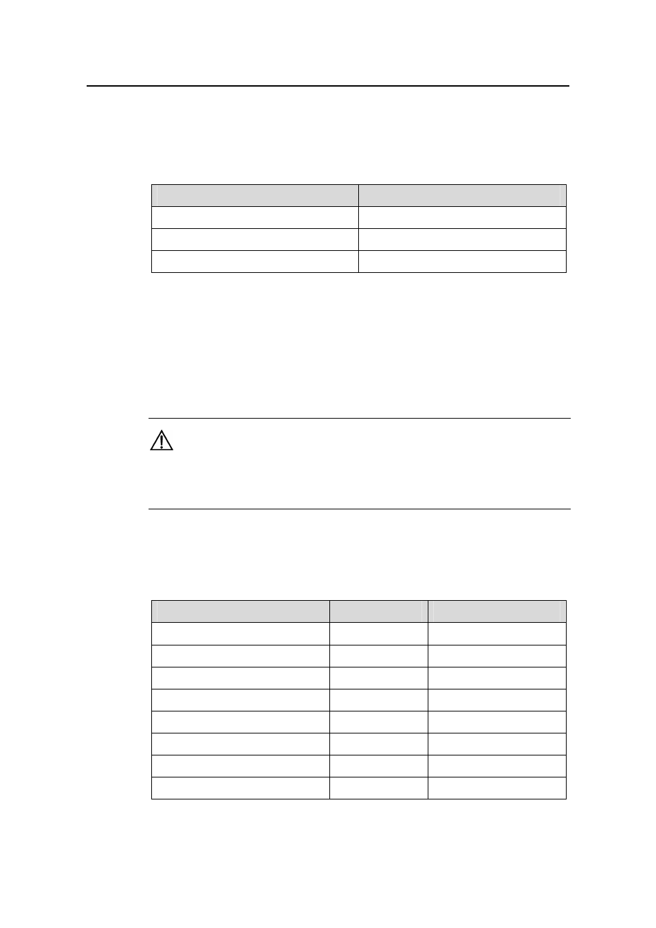
After installing the switch,
checking results are normal.
Table 4-4 Installation checking
verify the installation by the following list, ensuring all the
list
Item
Normal
Abnormal (Description)
ESD-preventive wrist strap
Console cable
PGND wire
Power cord
SRPU
LPU/service processor card
Fan tray
PS
U
- H3C S7500E Series Switches H3C S7500 Series Switches H3C S5800 Series Switches H3C S5820X Series Switches H3C S5500 Series Switches H3C S5120 Series Switches H3C S3610[S5510] Series Switches H3C S3600 Series Switches H3C S3100 Series Switches OAA For Routers H3C WX6000 Series Access Controllers H3C WX5000 Series Access Controllers H3C WX3000 Series Unified Switches H3C LSQM1WCMB0 Access Controller Module H3C LSBM1WCM2A0 Access Controller Module H3C WA2600 Series WLAN Access Points H3C WA2200 Series WLAN Access Points H3C SecPath F1000-E H3C SecPath F1000-A H3C SecPath F1000-S H3C SecPath F100-A H3C SecPath F100-C-EI H3C SecPath V100-E H3C SecCenter iTAS H3C Device Manager