4 connecting poe power cord, I. grounding poe chassis, 4 connecting poe power cord -15 – H3C Technologies H3C S9500 Series Switches User Manual
Page 84
Installation Manual
H3C S9500 Series Routing Switches
Chapter 4 Switch Installation
4-15
Note:
z
-48V: -48 V
z
RTN: -48 V working ground
z
PGND: prote
round
DC power supply
ction g
4.5.4 Connecting PoE Power Cord
Th
can use PSE4500-A external PoE power supply,
whi
through the PoE entry module.
PSE2500-A1 external PoE power supply, which is
connected to the switch through the PoE filter at the rear of the chassis, for the switch to
motely supply power to the connected PD devices.
e S9505/S9508/S9512 switch
ch is connected to the switch
The S9502 switch can use
re
Note:
This section only focuses on the cable connection between the external PoE power
supply and the S9500 series switch. For the installation of the external PoE power
supply, see the manual shipped with the power supply.
chassis
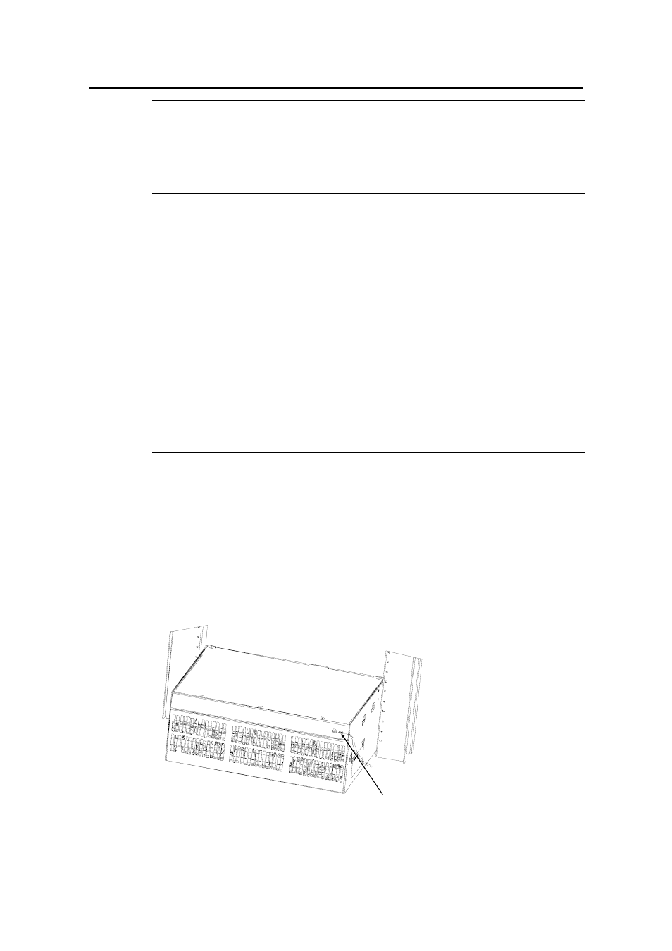
I. Grounding PoE
round the PoE chassis before connecting the PoE power cord to it. Follow
onnect the other end of the cable to the grounding bar or other grounding terminals.
You must g
these steps:
Connect the 6 AWG cable of the wiring terminal (with M6 hole) to the grounding screw
on the rear panel of the switch, as shown in Figure 4-16.
C
(1)
(1)
(1) Chassis grounding screw
- H3C S7500E Series Switches H3C S7500 Series Switches H3C S5800 Series Switches H3C S5820X Series Switches H3C S5500 Series Switches H3C S5120 Series Switches H3C S3610[S5510] Series Switches H3C S3600 Series Switches H3C S3100 Series Switches OAA For Routers H3C WX6000 Series Access Controllers H3C WX5000 Series Access Controllers H3C WX3000 Series Unified Switches H3C LSQM1WCMB0 Access Controller Module H3C LSBM1WCM2A0 Access Controller Module H3C WA2600 Series WLAN Access Points H3C WA2200 Series WLAN Access Points H3C SecPath F1000-E H3C SecPath F1000-A H3C SecPath F1000-S H3C SecPath F100-A H3C SecPath F100-C-EI H3C SecPath V100-E H3C SecCenter iTAS H3C Device Manager