Ii. other grounding environment – H3C Technologies H3C S9500 Series Switches User Manual
Page 77
Installation Manual
H3C S9500 Series Routing Switches
Chapter 4 Switch Installation
4-8
Step 4: Connect the other end of the ground wire to the ground bar of the switch.
Note:
Generally, the cabinets installed in equipment rooms are equipped with ground bar. In
this case, you can connect the PGND wire of the switch to the ground bar for it.
II. Other grounding environment
Following are some methods for grounding the switch in different grounding
environments that you are likely to encounter when installing the switch at different
places.
Note:
Rather than specifying the switch model or showing the actual location of the switch
power input or grounding screw, the following figures are primarily intended for
illustrating the switch grounding, either via grounding screw or power input, in specific
grounding environments.
z
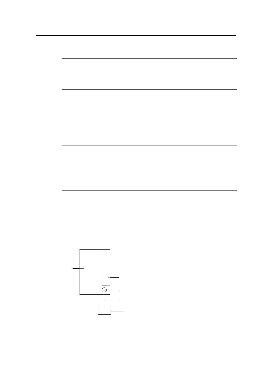
If a ground bar is available, attach one end of the yellow-green PGND wire of the
switch to a grounding bolt of the ground bar and fasten the captive nuts. Note that
the fire main and lightning rod of a building are not suitable for grounding the
switch. The PGND wire of the switch should be connected to the grounding device
in the equipment room. (For the S9500 series, the grounding screw is on the rear
panel. Connect it as illustrated in Figure 4-6).
(5)
(1)
(2)
(3)
(4)
(5)
(1)
(2)
(3)
(4)
(5)
(1)
(2)
(3)
(4)
(5)
(1)
(2)
(3)
(4)
(5)
(1)
(2)
(3)
(4)
(5)
(1)
(2)
(3)
(4)
(1) Air filter
(2) Grounding screw
(3) PGND wire
(4) Ground bar of the equipment room
(5) Rear panel of the switch
Figure 4-6 Ground the switch when ground bar is available
- H3C S7500E Series Switches H3C S7500 Series Switches H3C S5800 Series Switches H3C S5820X Series Switches H3C S5500 Series Switches H3C S5120 Series Switches H3C S3610[S5510] Series Switches H3C S3600 Series Switches H3C S3100 Series Switches OAA For Routers H3C WX6000 Series Access Controllers H3C WX5000 Series Access Controllers H3C WX3000 Series Unified Switches H3C LSQM1WCMB0 Access Controller Module H3C LSBM1WCM2A0 Access Controller Module H3C WA2600 Series WLAN Access Points H3C WA2200 Series WLAN Access Points H3C SecPath F1000-E H3C SecPath F1000-A H3C SecPath F1000-S H3C SecPath F100-A H3C SecPath F100-C-EI H3C SecPath V100-E H3C SecCenter iTAS H3C Device Manager