H3C Technologies H3C S9500 Series Switches User Manual
Page 91
Installation Manual
H3C S9500 Series Routing Switches
Chapter 4 Switch Installation
4-22
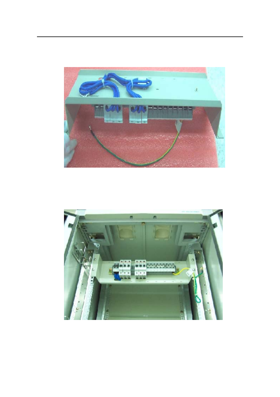
e air switches with 6mm
2
cables and
2
cable for grounding, as illustrated in Figure
z
Connect the DC input terminal blocks and th
fix the cable properly. Also use a 6mm
4-25.
Figure 4-25 Backplane Diagram for connecting DC input terminal blocks and air
switches
Fix the DC power distribution box onto the back of the cabinet, as illustrated in
Figure 4-26.
z
of the B68 cabinet
C power modules by
connecting the lower terminals of the air switches to DC power input terminals and
Figure 4-26 Diagram for fixing the power distribution box to the rear
z
You can make the air switches to supply power to D
This manual is related to the following products:
- H3C S7500E Series Switches H3C S7500 Series Switches H3C S5800 Series Switches H3C S5820X Series Switches H3C S5500 Series Switches H3C S5120 Series Switches H3C S3610[S5510] Series Switches H3C S3600 Series Switches H3C S3100 Series Switches OAA For Routers H3C WX6000 Series Access Controllers H3C WX5000 Series Access Controllers H3C WX3000 Series Unified Switches H3C LSQM1WCMB0 Access Controller Module H3C LSBM1WCM2A0 Access Controller Module H3C WA2600 Series WLAN Access Points H3C WA2200 Series WLAN Access Points H3C SecPath F1000-E H3C SecPath F1000-A H3C SecPath F1000-S H3C SecPath F100-A H3C SecPath F100-C-EI H3C SecPath V100-E H3C SecCenter iTAS H3C Device Manager