Ii. connecting fiber, 12 cable routing recommendations, 1 freestanding switch on tabletop – H3C Technologies H3C S9500 Series Switches User Manual
Page 97: 12 cable routing recommendations -28, 1 freestanding switch on tabletop -28
Installation Manual
H3C S9500 Series Routing Switches
Chapter 4 Switch Installation
4-28
Note:
z
When selecting a fiber network facility, make sure that the type of the connector and
z
Before connecting the fiber, make sure that the receive-end optical power does not
e receiving optical power. Excessive receiving
the fiber match the adopted optical port.
exceed the upper threshold of th
optical power is very likely to burn the optical module.
Fiber connectors are indispensable pa
communication system. Their application a
optical channels, which makes the optical syste
convenient and the transit dispatching of t
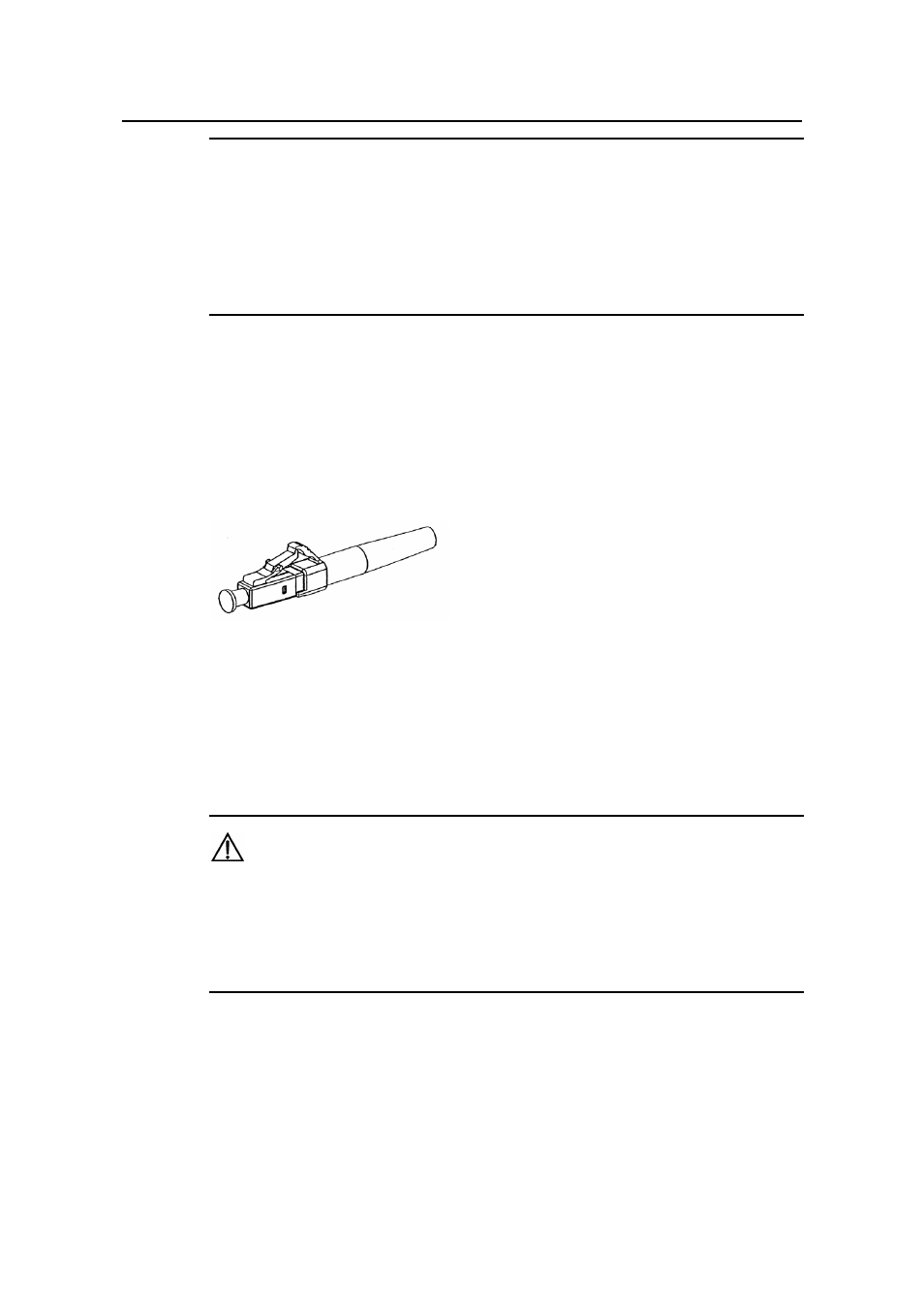
connectors, only LC connector will be intr
z
LC fiber connector
ssive components in an optical fiber
llows the removable connection between
m debugging and maintenance more
he system more flexible. Among various fiber
oduced here.
Figure 4-30 LC connector
II
d of the fiber into the SFP optical module of the S9500 series.
tep 2: Connect the other end of the fiber into the corresponding device.
. Connecting fiber
Step 1: Plug one en
S
Caution:
When the optical interface has not been connected with a fiber connector or its
ustproof mesh is open, there might be some invisible radiation emitted from the optical
interface. So do not look into the optical interface directly.
no connector plugged in.
d
Cover the optical interface if there is
4.12 Cable Routing Recommendations
4.12.1 Freestanding Switch on Tabletop
For only selling an integrated chassis, you do not have to care about the cabling inside
or outside the cabinet. All the LPU cables are routed from the left side of the chassis
- H3C S7500E Series Switches H3C S7500 Series Switches H3C S5800 Series Switches H3C S5820X Series Switches H3C S5500 Series Switches H3C S5120 Series Switches H3C S3610[S5510] Series Switches H3C S3600 Series Switches H3C S3100 Series Switches OAA For Routers H3C WX6000 Series Access Controllers H3C WX5000 Series Access Controllers H3C WX3000 Series Unified Switches H3C LSQM1WCMB0 Access Controller Module H3C LSBM1WCM2A0 Access Controller Module H3C WA2600 Series WLAN Access Points H3C WA2200 Series WLAN Access Points H3C SecPath F1000-E H3C SecPath F1000-A H3C SecPath F1000-S H3C SecPath F100-A H3C SecPath F100-C-EI H3C SecPath V100-E H3C SecCenter iTAS H3C Device Manager