Iii. electrical capacity of the terminal blocks, Iv. terminal block components, 2 installation of power distribution box – H3C Technologies H3C S9500 Series Switches User Manual
Page 90: 2 installation of power distribution box -21, 2 inst, Allation of power distribution box
Installation Manual
H3C S9500 Series Routing Switches
Chapter 4 Switch Installation
4-21
nt: 63 A
z
e: 600 V
2
z
Maximum current/maximum crimping area: 63 A/16 mm
2
III. Electrical capacity of the terminal blocks
z
Rated curre
Rated voltag
z
Rated cross-sectional area: 16 mm
IV. Terminal block components
Table 4-1illustrates terminal block components.
Table 4-1 Terminal block components
NO
Name
Quantity
1 End
bracket
2
2 Cross
connector
3
3 Marker
6
4 Terminal
11
5 Clapboard
7
6 Rail
1
7 Circuit
breaker
6
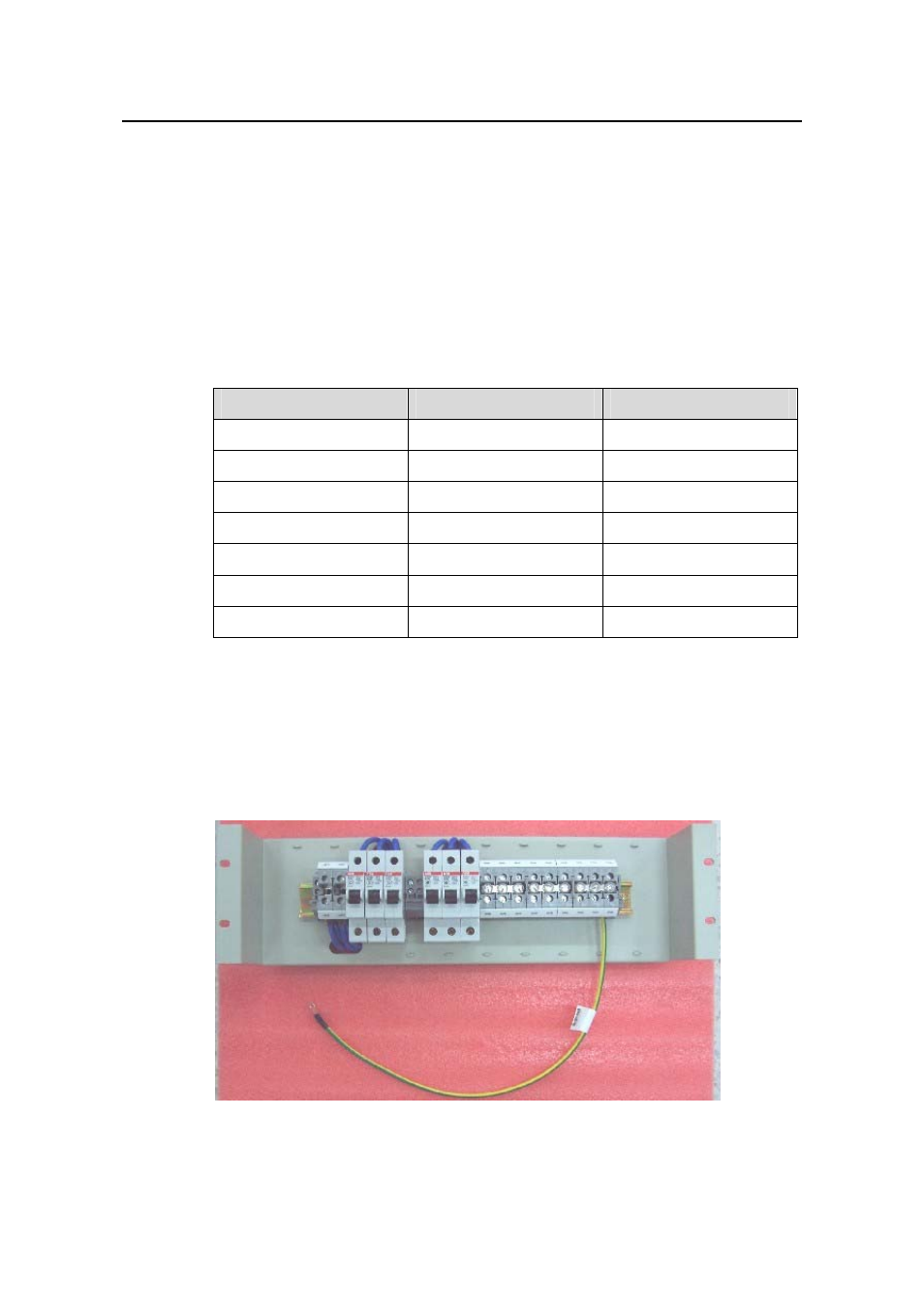
4.7.2 Inst
:
r switches to the cabinet via the rail, as
illustrated in Figure 4-24.
allation of Power Distribution Box
To install power distribution box, take the following steps
z
Install the DC input terminal blocks and ai
Figure 4-24 Install the DC input terminal blocks and air switches
- H3C S7500E Series Switches H3C S7500 Series Switches H3C S5800 Series Switches H3C S5820X Series Switches H3C S5500 Series Switches H3C S5120 Series Switches H3C S3610[S5510] Series Switches H3C S3600 Series Switches H3C S3100 Series Switches OAA For Routers H3C WX6000 Series Access Controllers H3C WX5000 Series Access Controllers H3C WX3000 Series Unified Switches H3C LSQM1WCMB0 Access Controller Module H3C LSBM1WCM2A0 Access Controller Module H3C WA2600 Series WLAN Access Points H3C WA2200 Series WLAN Access Points H3C SecPath F1000-E H3C SecPath F1000-A H3C SecPath F1000-S H3C SecPath F100-A H3C SecPath F100-C-EI H3C SecPath V100-E H3C SecCenter iTAS H3C Device Manager