H3C Technologies H3C S9500 Series Switches User Manual
Page 174
Installation Manual
H3C S9500 Series Routing Switches
Appendix B Installation of B68 Cabinet
B-23
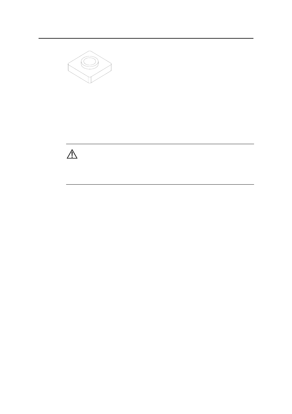
Figure B-24
Appearance of T nut
2) Leveling and fixing slide rail
Fix the slide rail on the support with T nut, flat washer, spring washer and bolt M12
× 20.
The installation is shown in Figure B-25.
Caution:
The slide rail should be installed with the slide shield facing outward as illustrated in
Figure B-25.
First, screw the bolt M12
×20 with spring washer and flat washer (do not tighten the
screws at this time, just make sure they will not drop), and then insert the bolts into the
support holes in sequence. Measure (in transverse and longitudinal directions) the
segments of the slide rail with a horizontal ruler to check whether the bubble in the
horizontal ruler is right in the middle. If it is horizontal, screw tight the bolts in sequence
and measure the level once again as shown in Figure B-26. Otherwise, loosen the
screws and adjust them by adding or removing the washers. After the slide rail is
installed, the following requirements should be met:
z
A single slide rail should be horizontal in longitudinal direction.
z
Two parallel slide rails should be horizontal in transverse direction.
z
The distance between the central lines of two parallel slide rails should be
720mm±1mm.
z
When checked with a straight line, multiple slide rails interconnected should also
form a straight line. No gap or height difference between the joints is allowed.
- H3C S7500E Series Switches H3C S7500 Series Switches H3C S5800 Series Switches H3C S5820X Series Switches H3C S5500 Series Switches H3C S5120 Series Switches H3C S3610[S5510] Series Switches H3C S3600 Series Switches H3C S3100 Series Switches OAA For Routers H3C WX6000 Series Access Controllers H3C WX5000 Series Access Controllers H3C WX3000 Series Unified Switches H3C LSQM1WCMB0 Access Controller Module H3C LSBM1WCM2A0 Access Controller Module H3C WA2600 Series WLAN Access Points H3C WA2200 Series WLAN Access Points H3C SecPath F1000-E H3C SecPath F1000-A H3C SecPath F1000-S H3C SecPath F100-A H3C SecPath F100-C-EI H3C SecPath V100-E H3C SecCenter iTAS H3C Device Manager