I. appearance, Ii. electrical performance of the terminal block, 2 power distribution box – H3C Technologies H3C S9500 Series Switches User Manual
Page 86: 2 power distribution box -17, 2 pow tribution box, Er dis
Installation Manual
H3C S9500 Series Routing Switches
Chapter 4 Switch Installation
4-17
I. Appearance
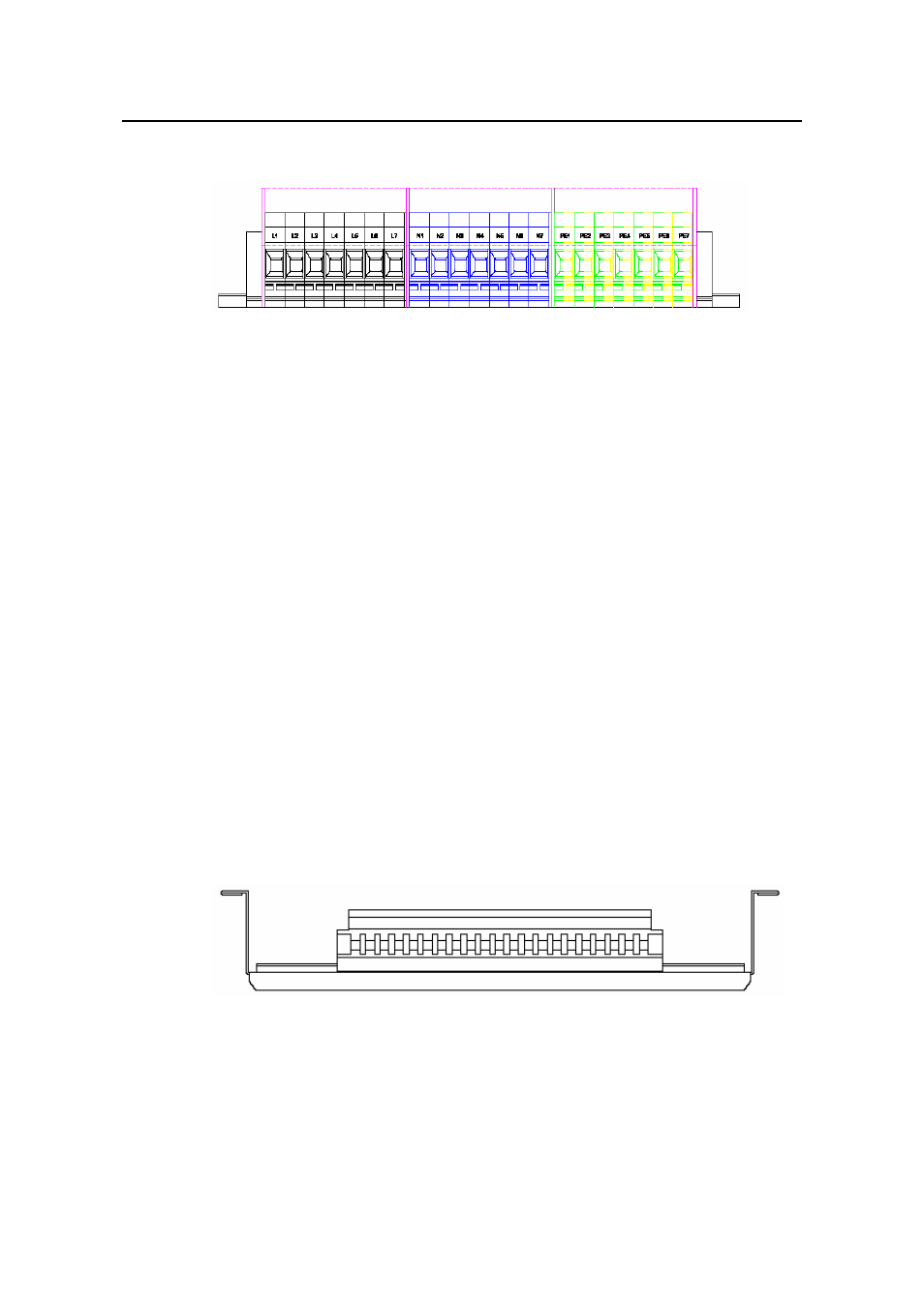
nal block structure diagram
nals,
rts are
s are
z
The yellow-green terminals from PE1 to PE7 are output ports for earth wire. These
II. Electrical performance of the terminal block
Inpu
z
z
4.6.2 Pow
tribution Box
I.
p
Figure 4-18 Termi
The terminal block has 21 terminals to connect power cords: seven gray termi
seven blue terminals and seven yellow-green terminals.
z
The gray terminals from L1 to L7 are output ports for live wire. These po
connected to each other.
z
The blue terminals from N1 to N7 are output ports for neutral wire. These port
connected to each other.
ports are connected to each other and connected to the cabinet.
t:
z
Rated current: 76 A
Rated voltage: 1000 V
z
Rated cross-sectional area: 16 mm
2
Maximum current/maximum crimping area: 101 A/25 mm
2
Output: seven loop outputs.
er Dis
Ap earance
Figure 4-19 Front view of the power distribution box
- H3C S7500E Series Switches H3C S7500 Series Switches H3C S5800 Series Switches H3C S5820X Series Switches H3C S5500 Series Switches H3C S5120 Series Switches H3C S3610[S5510] Series Switches H3C S3600 Series Switches H3C S3100 Series Switches OAA For Routers H3C WX6000 Series Access Controllers H3C WX5000 Series Access Controllers H3C WX3000 Series Unified Switches H3C LSQM1WCMB0 Access Controller Module H3C LSBM1WCM2A0 Access Controller Module H3C WA2600 Series WLAN Access Points H3C WA2200 Series WLAN Access Points H3C SecPath F1000-E H3C SecPath F1000-A H3C SecPath F1000-S H3C SecPath F100-A H3C SecPath F100-C-EI H3C SecPath V100-E H3C SecCenter iTAS H3C Device Manager