8 installing cabling rack, 9 installing fan tray, 8 installing cabling rack -23 – H3C Technologies H3C S9500 Series Switches User Manual
Page 92: 9 installing fan tray -23, 8 inst, Alling cabling rack, Alling fan tray 4.9 inst
Installation Manual
H3C S9500 Series Routing Switches
Chapter 4 Switch Installation
4-23
z
an use the BGND and PGND terminal blocks as needed. The rightmost
s, as
ower
tion box.
of the cabinet,
4.8 Inst
ake the
e and a
rack for S9505/S9508 and two for S9512);
supply voltages to DC power. (Refer to Figure 4-23 for detail. Note that the
diameter of the cables need to be 6mm
2
or 10mm
2
.)
You c
PGND terminals must be connected to the cabinet using a 6mm
2
cable
illustrated in Figure 4-26.
z
Fasten the connected power cables with a wire and secure them onto the p
distribution box.
z
Use two 16mm
2
cables to connect the cabinet and the DC power distribu
You need to connect the two cables to the leftmost terminal blocks
as illustrated in Figure 4-23.
alling Cabling Rack
For your convenience, cabling racks are shipped with the S9500 series. T
following steps to install the rack.
Step 1: Face the LPU slots of the switch;
Step 2: Attach the left mounting ear (the one with an elliptical hole on one surfac
recessed hole on the other) onto the cabling rack and fix it with screws (one cabling
Step 3: Install mounting ears onto the both sides of the switch.
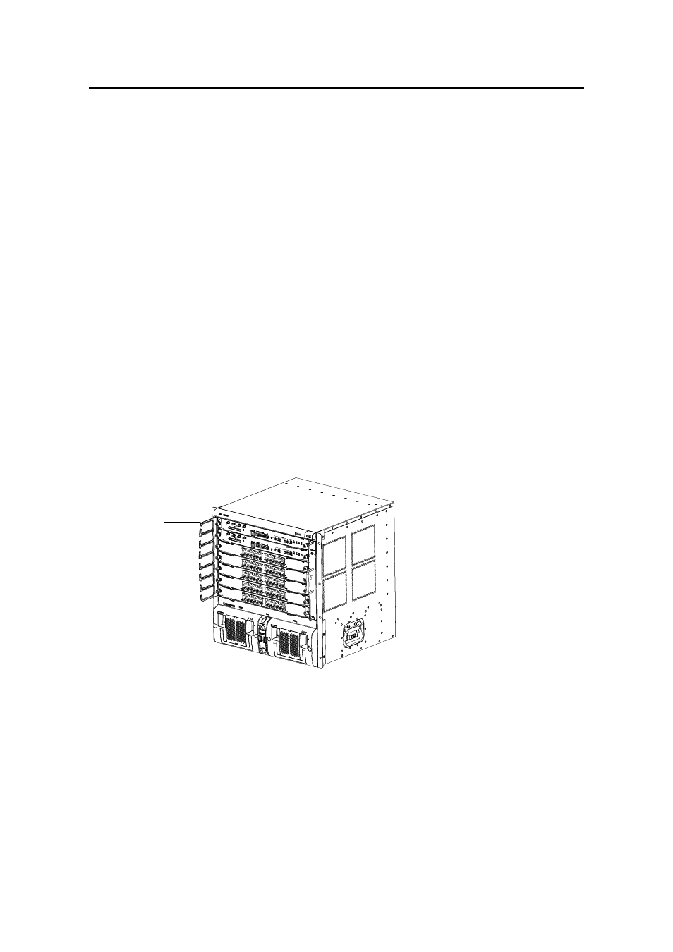
Cabling rack
Cabling rack
Figure 4-27 The position of the cabling rack
alling Fan Tray
4.9 Inst
The fan tray is hot swappable.
- H3C S7500E Series Switches H3C S7500 Series Switches H3C S5800 Series Switches H3C S5820X Series Switches H3C S5500 Series Switches H3C S5120 Series Switches H3C S3610[S5510] Series Switches H3C S3600 Series Switches H3C S3100 Series Switches OAA For Routers H3C WX6000 Series Access Controllers H3C WX5000 Series Access Controllers H3C WX3000 Series Unified Switches H3C LSQM1WCMB0 Access Controller Module H3C LSBM1WCM2A0 Access Controller Module H3C WA2600 Series WLAN Access Points H3C WA2200 Series WLAN Access Points H3C SecPath F1000-E H3C SecPath F1000-A H3C SecPath F1000-S H3C SecPath F100-A H3C SecPath F100-C-EI H3C SecPath V100-E H3C SecCenter iTAS H3C Device Manager