Appendix c lightning protection of the switch, Figure c-1 diagram of lightning arrester – H3C Technologies H3C S9500 Series Switches User Manual
Page 190

Installation Manual
H3C S9500 Series Routing Switches
Appendix C Lightning Protection of the Switch
C-1
Appendix C Lightning Protection of the Switch
C.1 Installation of Lightning Arrester for AC Power (Socket
Strip with Lightning Protection)
Caution:
Lightning arrester will not be shipped with the switch. You should purchase it by
yourself if needed.
If an outdoor AC power cord should be directly led to the switch, please serially connect
the lightning arrester for AC power (Socket Strip with Lightning Protection) before you
plug AC power cord into the switch, thus to prevent the possible damage to the switch
due to lightning strike. You can use cable clips and screws to fasten the lightning
arrester for AC power on the cabinet, workbench or the wall of equipment room.
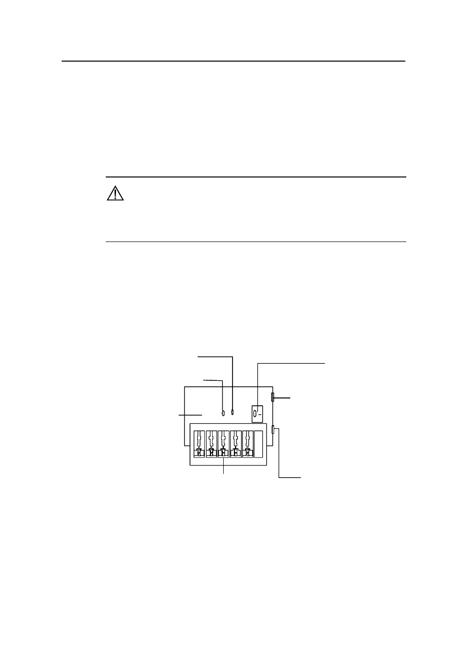
Mainboard
Grounding and pol arity indic ator (red) :
On means that the lines are wr ongly connected
(either the ground wire is not well connec ted, or the live and zero li nes are wrongly c o
Pleas e chec k t he power suppl y circuit.
Power
Normal operation indicator (green):
On means t hat the arrest er wor ks normally. Other wise, it
means t hat the protec tion circuit has been damaged.
Multipurpose power soc ket, connected t o the devic e
protected by t he arrester
Power soc ket (complied
connect ed t o the power
through power cord
Overload auto prot
whic h can be ma
nnected).
s witch
wit h IEC s tandard),
suppl y of the equipment room
ect or,
nually reset.
Figure C-1 Diagram of lightning arrester
- H3C S7500E Series Switches H3C S7500 Series Switches H3C S5800 Series Switches H3C S5820X Series Switches H3C S5500 Series Switches H3C S5120 Series Switches H3C S3610[S5510] Series Switches H3C S3600 Series Switches H3C S3100 Series Switches OAA For Routers H3C WX6000 Series Access Controllers H3C WX5000 Series Access Controllers H3C WX3000 Series Unified Switches H3C LSQM1WCMB0 Access Controller Module H3C LSBM1WCM2A0 Access Controller Module H3C WA2600 Series WLAN Access Points H3C WA2200 Series WLAN Access Points H3C SecPath F1000-E H3C SecPath F1000-A H3C SecPath F1000-S H3C SecPath F100-A H3C SecPath F100-C-EI H3C SecPath V100-E H3C SecCenter iTAS H3C Device Manager
