B.3.3 support positioning, I. planning the cabinet position, Ii. drawing lines – H3C Technologies H3C S9500 Series Switches User Manual
Page 168
Installation Manual
H3C S9500 Series Routing Switches
Appendix B Installation of B68 Cabinet
B-17
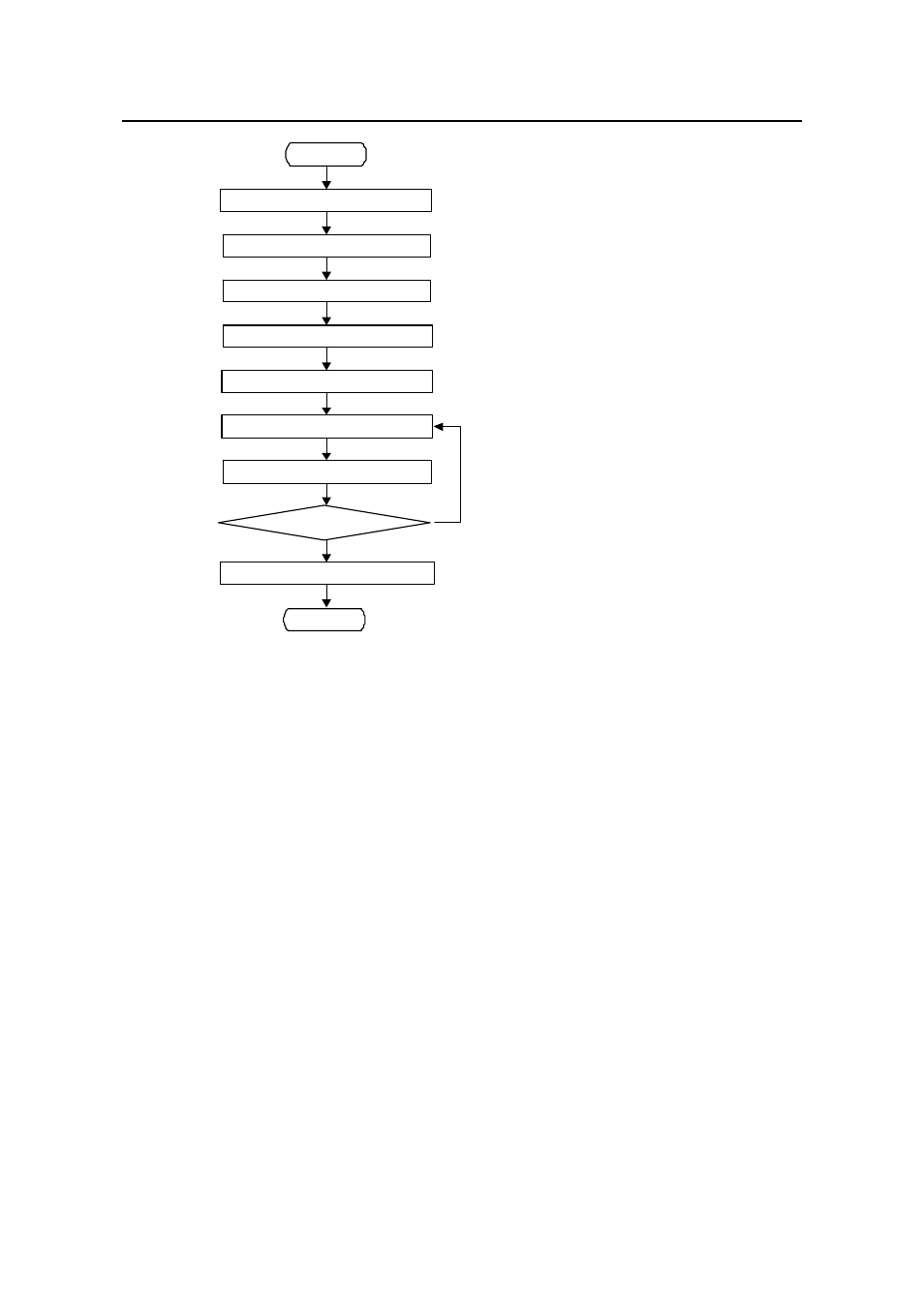
Start
Install anti-static floor supporting
accessories
Test passed?
Y
N
Support positioning
Install support
Install slide rail
Level cabinet
Fasten cabinet
Insulation test
Recover floor
End
Start
Install anti-static floor supporting
accessories
Test passed?
Y
N
Support positioning
Install support
Install slide rail
Level cabinet
Fasten cabinet
Insulation test
Recover floor
End
Figure B-17
Installation flowchart of the B68-22 cabinet (on raised floor)
B.3.3 Support Positioning
I. Planning the cabinet position
Before the installation, first plan the available space. There should be sufficient space
for maintenance and operation at the front and rear doors of the cabinet, as shown in
Figure B-19, Figure B-20 and Figure B-21. At least 800mm clearance is required
around the B68-22 cabinet.
II. Drawing lines
According to the reference dimension and support dimension in the construction plane
design diagram, determine the support installation location, measure several
marking-out points, mark out two lines which are parallel with the reference and whose
spacing is 760mm. According to the design requirements, determine the hole locations
of the first support on the two lines. Then take the hole as the reference point and mark
out the installation holes of other supports one by one. To avoid faults, after being
marked out, all hole location lines should be measured again so as to ensure the proper
dimension. Figure B-18 shows the support installation hole locations, Figure B-19
shows the installation hole locations of a single cabinet, Figure B-20 shows the
- H3C S7500E Series Switches H3C S7500 Series Switches H3C S5800 Series Switches H3C S5820X Series Switches H3C S5500 Series Switches H3C S5120 Series Switches H3C S3610[S5510] Series Switches H3C S3600 Series Switches H3C S3100 Series Switches OAA For Routers H3C WX6000 Series Access Controllers H3C WX5000 Series Access Controllers H3C WX3000 Series Unified Switches H3C LSQM1WCMB0 Access Controller Module H3C LSBM1WCM2A0 Access Controller Module H3C WA2600 Series WLAN Access Points H3C WA2200 Series WLAN Access Points H3C SecPath F1000-E H3C SecPath F1000-A H3C SecPath F1000-S H3C SecPath F100-A H3C SecPath F100-C-EI H3C SecPath V100-E H3C SecCenter iTAS H3C Device Manager