H3C Technologies H3C S9500 Series Switches User Manual
Page 172
Installation Manual
H3C S9500 Series Routing Switches
Appendix B Installation of B68 Cabinet
B-21
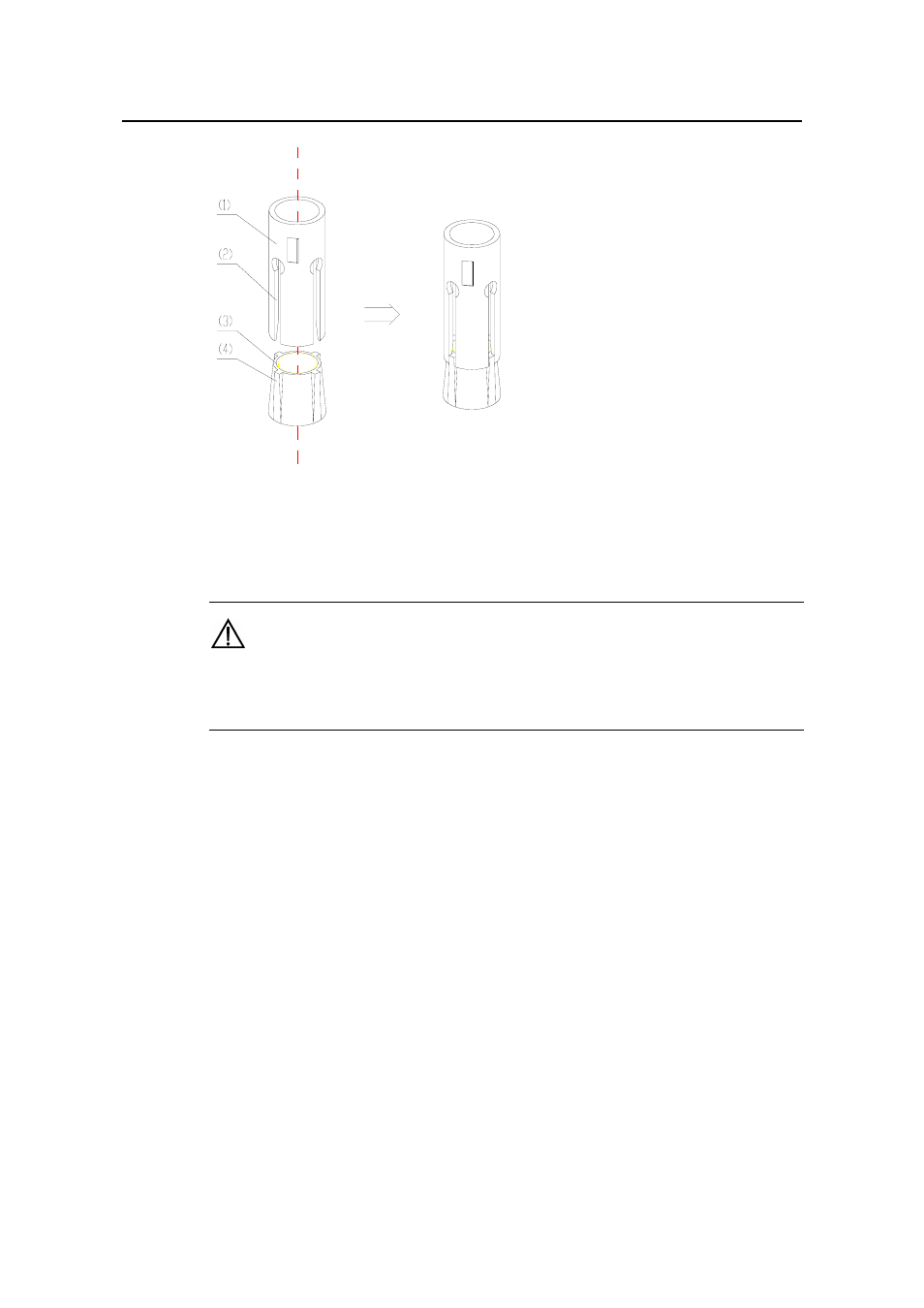
(1) Expansion tube
(2) Guide trough of expansion tube
(3) Expansion nut
(4) Guide rib of expansion nut
Figure B-22
Installation of expansion tube and expansion nut
Caution:
The guide rib of expansion nut must be inserted in advance into the guide trough of the
expansion tube, or the expansion bolt cannot be installed and fastened properly.
2) Adjusting height of the support
According to the floor height measured and the height scale on the support, adjust
height of all supports and fasten the height-retaining bolt to 45 Nm with a torque
spanner. Here, first fasten the middle bolts, and then the side bolts. See Figure B-23.
3) Installing and fixing the support
Clean the ground and support surface, align the support installation hole with the
corresponding expansion bolt according to Figure B-23 and fix the support on the
ground with the bolt, spring washer and big flat washer. The fastening force moment
should be 45 Nm.
The bolts used to fix the support should be fastened in diagonally in sequence to
reduce the stress between the bolts and support. It is also for the convenience of
support adjusting during the installation. Install other supports according to the above
method. The connection between the support and ground is shown in Figure B-23:
- H3C S7500E Series Switches H3C S7500 Series Switches H3C S5800 Series Switches H3C S5820X Series Switches H3C S5500 Series Switches H3C S5120 Series Switches H3C S3610[S5510] Series Switches H3C S3600 Series Switches H3C S3100 Series Switches OAA For Routers H3C WX6000 Series Access Controllers H3C WX5000 Series Access Controllers H3C WX3000 Series Unified Switches H3C LSQM1WCMB0 Access Controller Module H3C LSBM1WCM2A0 Access Controller Module H3C WA2600 Series WLAN Access Points H3C WA2200 Series WLAN Access Points H3C SecPath F1000-E H3C SecPath F1000-A H3C SecPath F1000-S H3C SecPath F100-A H3C SecPath F100-C-EI H3C SecPath V100-E H3C SecCenter iTAS H3C Device Manager