11 connecting interface cables, 1 connecting console cable, I. introduction – H3C Technologies H3C S9500 Series Switches User Manual
Page 94: 11 connecting interface cables -25, 1 connecting console cable -25, 11 co, Nnecting interface cables, 1 co, Nnecting console cable
Installation Manual
H3C S9500 Series Routing Switches
Chapter 4 Switch Installation
4-25
te:
No
Put the removed blank filler panel away for future use.
For the S9500 series, the service processor card can be installed in the LPU slot in the
same way as installing the LPU board.
4.11 Co
4.11.1 Co
I.
-9 (female) connector. You can plug it into the 9-pin (male) serial port
nnecting Interface Cables
nnecting Console Cable
Introduction
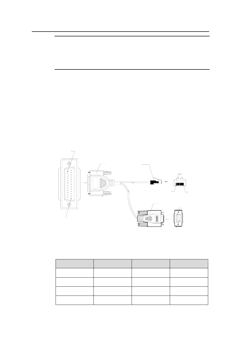
Console cable is an 8-core shielded cable. At one end of the cable is a crimped RJ-45
connector that is to be plugged into the console port of the switch. At the other end of
the cable is a DB
on the console terminal. The following figure illustrates the console cable.
Enlarged A side
Pos. 25
DB 25 Female
8P8C Plug
Enlarged B side
B
A
Pos.8
Pos.1
DB9 Female
Enlarged C side
Pos.1
C
Pos.1
Pos.9
Figure 4-28 Console cable
Table 4-2 Console cable pinouts
RJ-45
Signal
DB-9
Signal
1 RTS
8 CTS
2 DTR
6 DSR
3 TXD
2 RXD
4 CD
5 SG
- H3C S7500E Series Switches H3C S7500 Series Switches H3C S5800 Series Switches H3C S5820X Series Switches H3C S5500 Series Switches H3C S5120 Series Switches H3C S3610[S5510] Series Switches H3C S3600 Series Switches H3C S3100 Series Switches OAA For Routers H3C WX6000 Series Access Controllers H3C WX5000 Series Access Controllers H3C WX3000 Series Unified Switches H3C LSQM1WCMB0 Access Controller Module H3C LSBM1WCM2A0 Access Controller Module H3C WA2600 Series WLAN Access Points H3C WA2200 Series WLAN Access Points H3C SecPath F1000-E H3C SecPath F1000-A H3C SecPath F1000-S H3C SecPath F100-A H3C SecPath F100-C-EI H3C SecPath V100-E H3C SecCenter iTAS H3C Device Manager