H3C Technologies H3C S9500 Series Switches User Manual
Page 80
Installation Manual
H3C S9500 Series Routing Switches
Chapter 4 Switch Installation
4-11
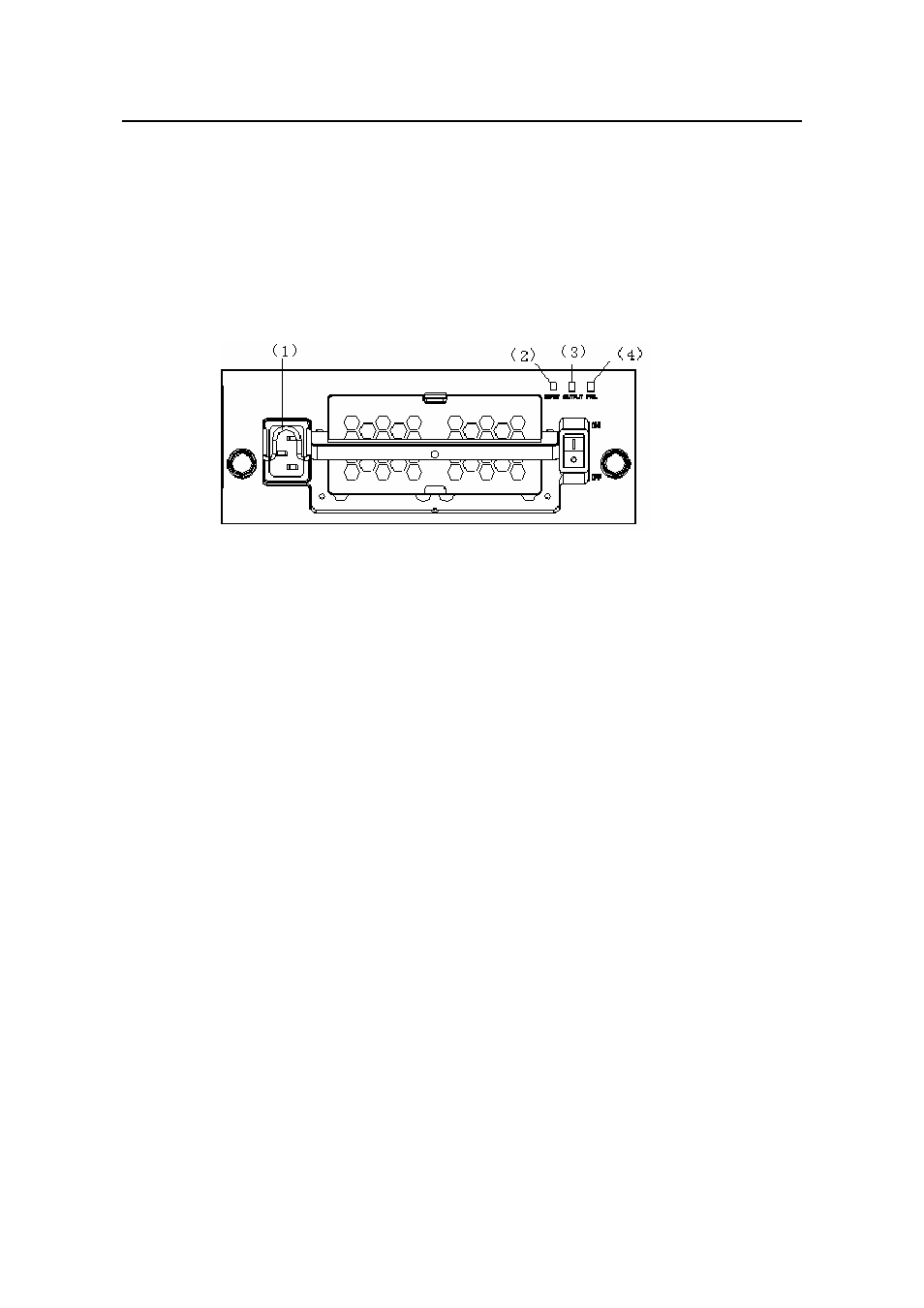
ect AC power cord for the S9502:
Step 1: Pull up the clamp at the left of the PSU front panel.
e
soc
e
Ste
e other end of the power cord into the external power socket for the
ch.
Conn
St p 2: Insert one end of the AC power cord accompanied with the switch into the
ket on the PSU unit.
St p 3: Pull down the clamp to hold the power connecter.
p 4: Insert th
swit
ut LED
(4) Fail LED
t.
h the switch into the
f the power c
ower jack for the switch.
(1) connector-retention clamp
(2) Input LED
(3) Outp
Figure 4-10 Connect AC power cord for the S9502
Connect AC power cord for the S9505/S9508/S9512:
Step 1: Pull the clamp at the left of the PSU front panel to the righ
Step 2: Insert one end of the AC power cord accompanied wit
socket on the PSU unit.
Step 3: Pull the clamp to the left to hold the power connector.
Step 4: Insert the other end o
ord into the p
- H3C S7500E Series Switches H3C S7500 Series Switches H3C S5800 Series Switches H3C S5820X Series Switches H3C S5500 Series Switches H3C S5120 Series Switches H3C S3610[S5510] Series Switches H3C S3600 Series Switches H3C S3100 Series Switches OAA For Routers H3C WX6000 Series Access Controllers H3C WX5000 Series Access Controllers H3C WX3000 Series Unified Switches H3C LSQM1WCMB0 Access Controller Module H3C LSBM1WCM2A0 Access Controller Module H3C WA2600 Series WLAN Access Points H3C WA2200 Series WLAN Access Points H3C SecPath F1000-E H3C SecPath F1000-A H3C SecPath F1000-S H3C SecPath F100-A H3C SecPath F100-C-EI H3C SecPath V100-E H3C SecCenter iTAS H3C Device Manager