H3C Technologies H3C S9500 Series Switches User Manual
Page 16
Installation Manual
H3C S9500 Series Routing Switches
Chapter 1 Product Overview
1-10
Note:
The external PoE power system supports 2+1 redundancy and online-swap.
Dedicated interface module is required for the PoE power supply on switches. On the
S9500 series, it is the GV48 interface module.
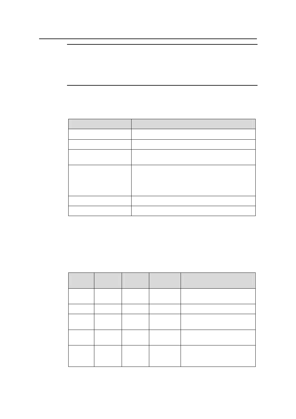
Table 1-3 describes the technical specifications of the external PoE power system.
Table 1-3
Technical specifications of the PoE power system
Item
Description
Dimensions (H
× W × D)
177
× 486 × 320.5 mm (7.0 × 19.1 × 12.6 in.)
System controller
One
Rectifier
Two NP2500UAC (required) + one redundant
NP2500UAC (optional)
AC distribution assembly
Three AC inputs with one manual switch for each
Three-phase AC voltage detection circuit
Input voltage range: 90 VAC to 290 VAC; rated voltage
and current: 250 VAC/20A
DC distribution assembly
A single DC output, with max output current of 93A
Max. power consumption
4500 W
PoE power system functions in monitoring and provides an RS232 and two RS485
monitoring interfaces. The system monitor sends the running information of the system
module to SRP through RS232 or RS485 interfaces and displays the alarm by ALM
LED. You can connect cables to the interface from the front or rear of the frame.
Table 1-4
LEDs of PoE power system
LED
Color
Normal
status
Abnormal
status
Causes
AC Green
ON OFF
There is no AC input or the fuse
is broken.
DC
Green
ON
OFF
There is no DC output.
Fault Red OFF ON
The fault in the module is
irretrievable.
RUN Green ON OFF
The power module is not
running or is failed.
ALM Red OFF ON
There is under- and
over-voltage, even no AC
power input, or faulty module.
- H3C S7500E Series Switches H3C S7500 Series Switches H3C S5800 Series Switches H3C S5820X Series Switches H3C S5500 Series Switches H3C S5120 Series Switches H3C S3610[S5510] Series Switches H3C S3600 Series Switches H3C S3100 Series Switches OAA For Routers H3C WX6000 Series Access Controllers H3C WX5000 Series Access Controllers H3C WX3000 Series Unified Switches H3C LSQM1WCMB0 Access Controller Module H3C LSBM1WCM2A0 Access Controller Module H3C WA2600 Series WLAN Access Points H3C WA2200 Series WLAN Access Points H3C SecPath F1000-E H3C SecPath F1000-A H3C SecPath F1000-S H3C SecPath F100-A H3C SecPath F100-C-EI H3C SecPath V100-E H3C SecCenter iTAS H3C Device Manager