B1 or – Delta Electronics AC Motor Drive VFD-E User Manual
Page 42
Chapter 2 Installation and Wiring|
Revision June 2008, 04EE, SW--PW V1.11/CTL V2.11
2-15
The factory setting of the operation direction is forward running. The methods to control
the operation direction are: method 1, set by the communication parameters. Please refer
to the group 9 for details. Method2, control by the optional keypad KPE-LE02. Refer to
Appendix B for details.
When it needs to install the filter at the output side of terminals U/T1, V/T2, W/T3 on the
AC motor drive. Please use inductance filter. Do not use phase-compensation capacitors
or L-C (Inductance-Capacitance) or R-C (Resistance-Capacitance), unless approved by
Delta.
DO NOT connect phase-compensation capacitors or surge absorbers at the output
terminals of AC motor drives.
Use well-insulated motor, suitable for inverter operation.
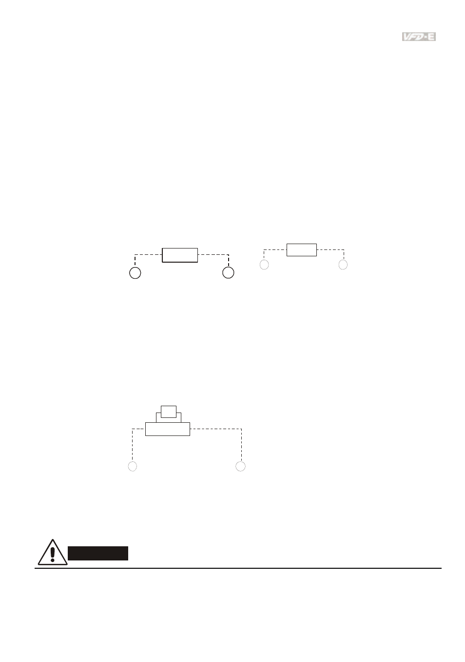
Terminals [+/B1, B2] for connecting brake resistor
B2
BR
+/B1
or
B2
BR
B1
for m od els VFDxxExxT
Connect a brake resistor or brake unit in applications with frequent deceleration ramps,
short deceleration time, too low brake torque or requiring increased brake torque.
If the AC motor drive has a built-in brake chopper (frame B, frame C and VFDxxxExxT
models), connect the external brake resistor to the terminals [+/B1, B2].
Models of frame A don’t have a built-in brake chopper. Please connect an external
optional brake unit (BUE-series) and brake resistor. Refer to BUE series user manual for
details.
BUE
BR
+
-
Brake resistor/unit(optional)
Please refer to Appendix B for details.
Connect the terminals [+(P), -(N)] of the brake unit to the AC motor drive terminals [+/B1, -
]. The length of wiring should be less than 5m with cable.
When not used, please leave the terminals [+/B1, -] open.
WARNING!
Short-circuiting [B2] or [-] to [+/B1] can damage the AC motor drive.