Delta Electronics AC Motor Drive VFD-E User Manual
Page 105
Chapter 4 Parameters|
4-52
Revision June 2008, 04EE, SW--PW V1.11/CTL V2.11
Settings
0
First
Master Frequency Command Only
1
First Master Frequency + Second Master Frequency
2
First Master Frequency - Second Master Frequency
02.02
Stop Method
Factory Setting: 0
Settings
0
STOP: ramp to stop
E.F.: coast to stop
1
STOP: coast to stop
E.F.: coast to stop
2
STOP: ramp to stop
E.F.: ramp to stop
3
STOP: coast to stop
E.F.: ramp to stop
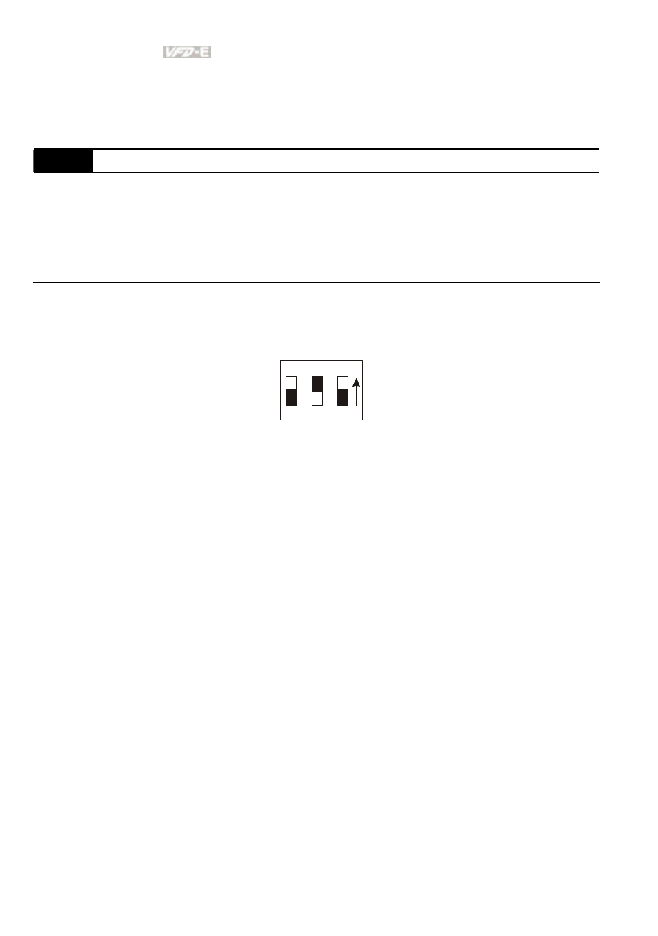
When the 2
nd
switch on the upper-right corner is set to be ON as shown in the following
diagram, the motor stop method (Pr.02.02) will force setting to 1. This setting (Pr.02.02) can’t
be changed till the 2nd switch is set to be OFF.
ON
1
2
3
The parameter determines how the motor is stopped when the AC motor drive receives a valid
stop command or detects External Fault.
Ramp:
the AC motor drive decelerates to Minimum Output Frequency (Pr.01.05)
according to the deceleration time and then stops.
Coast:
the AC motor drive stops the output instantly upon command, and the motor
free runs until it comes to a complete standstill.
The motor stop method is usually determined by the characteristics of the motor load and
how frequently it is stopped.
(1)
It is recommended to use “ramp to stop” for safety of personnel or to prevent
material from being wasted in applications where the motor has to stop after the
drive is stopped. The deceleration time has to be set accordingly.
(2)
If motor free running is allowed or the load inertia is large, it is recommended to
select “coast to stop”. For example: blowers, punching machines, centrifuges
and pumps.