Delta Electronics AC Motor Drive VFD-E User Manual
Page 17
Chapter 1 Introduction|
1-4
Revision June 2008, 04EE, SW--PW V1.11/CTL V2.11
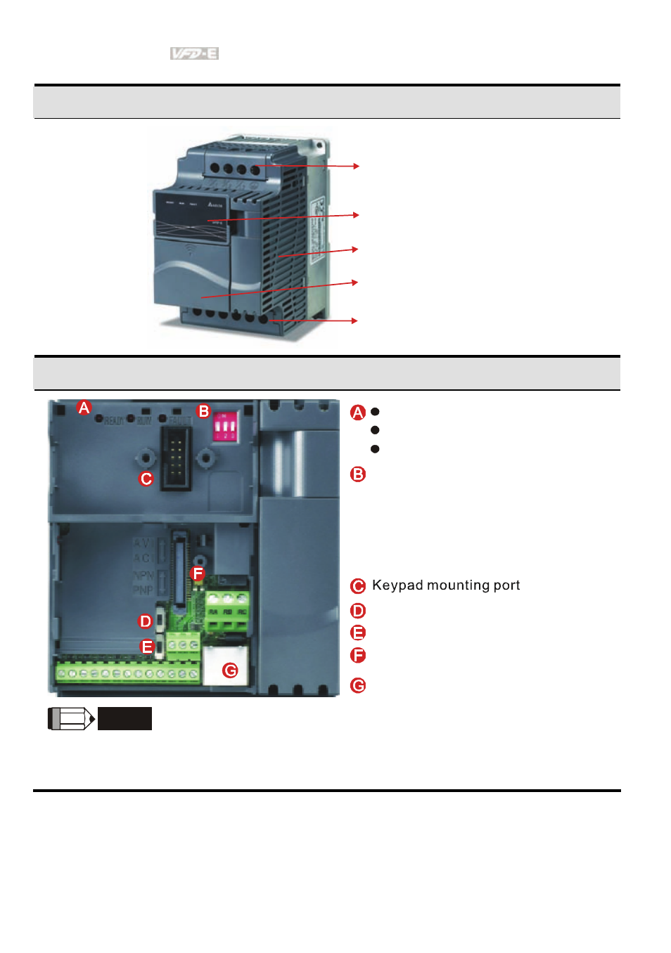
1-15HP/0.75-11kW (Frame B&C)
Input terminals cover
(R/L1, S/L2, T/L3)
Case body
Keypad cover
Output terminals cover
(U/T1, V/T2, W/T3)
Control board cover
Internal Structure
1.
2.
3.
READY: power indicator
RUN: status indicator
FAULT: fault indicator
NPN/PNP
RS485 port (RJ-45)
Switch to ON for 50Hz, refer to
P 01.00 to P01.02 for details
Switch to ON for free run to stop
refer to P02.02
Switch to ON for setting frequency
source to ACI (P 02.00=2)
ACI terminal (ACI/AVI2 switch )
Mounting port for extension card
NOTE
The LED “READY” will light up after applying power. The light won’t be off until the capacitors are
discharged to safe voltage levels after power off.
See also other documents in the category Delta Electronics Tools:
- AC Motor Drive VFD-G (183 pages)
- SMT Power Inductor SIL104R (1 page)
- Q48SB (2 pages)
- Planar DC/DC Transformer ER/ER(Plate) 22 (1 page)
- SMT Power Inductor HCB1190B (1 page)
- Series E48SR (15 pages)
- E48SR12007 (15 pages)
- SMT Power Inductor SIWC1360 (1 page)
- PFC Chokes PFC2815V Series (1 page)
- SMT Power Inductor SIB86 (1 page)
- PMC-24V050W1AA (2 pages)
- SMT Power Inductor HCB1050 (1 page)
- SMT Power Inductor HAH1330 (1 page)
- PFC Chokes PFC4120V Series (1 page)
- PFC Choke PFC3520V Series (1 page)
- SMT Power Inductor HCB1047B (1 page)
- SMT Power Inductor HAH1365 (1 page)
- SMT Power Inductor HMS1355 (1 page)
- Series S48SA (13 pages)
- E48SC (2 pages)
- SMT Power Inductor SILM106 (1 page)
- Delphi Series L48DB (2 pages)
- S48SA (13 pages)
- E36SR (2 pages)
- 3KVA (31 pages)
- SMT Power Inductor HMU1056L (1 page)
- Through Hole Power Inductors THCBR1090 (1 page)
- SMT Power Inductor SIL625 (1 page)
- SMT Power Inductor 1378(S) (1 page)
- Through Hole Power Inductors 1411 (1 page)
- Current Sense Transformers TCE1310H (1 page)
- H48SR (13 pages)
- Series E48SH (15 pages)
- AC Motor Drive VFD-EL (209 pages)
- Through Hole Power Inductors THAH1095 (1 page)
- Suppression Inductors LFU09V (1 page)
- SMT Power Inductor HCB0740A (1 page)
- Power Output Module DVPPS01 (2 pages)
- SMT Power Inductor SIR74 (1 page)
- L36SA (2 pages)
- 4.5V~ 5.5V (3 pages)
- Delphi Series V48SB (2 pages)
- Series S48SP (14 pages)
- Series 240W (11 pages)
- Delphi Series E24SR (15 pages)