Im 3 – Delta Electronics AC Motor Drive VFD-E User Manual
Page 34
Chapter 2 Installation and Wiring|
Revision June 2008, 04EE, SW--PW V1.11/CTL V2.11
2-7
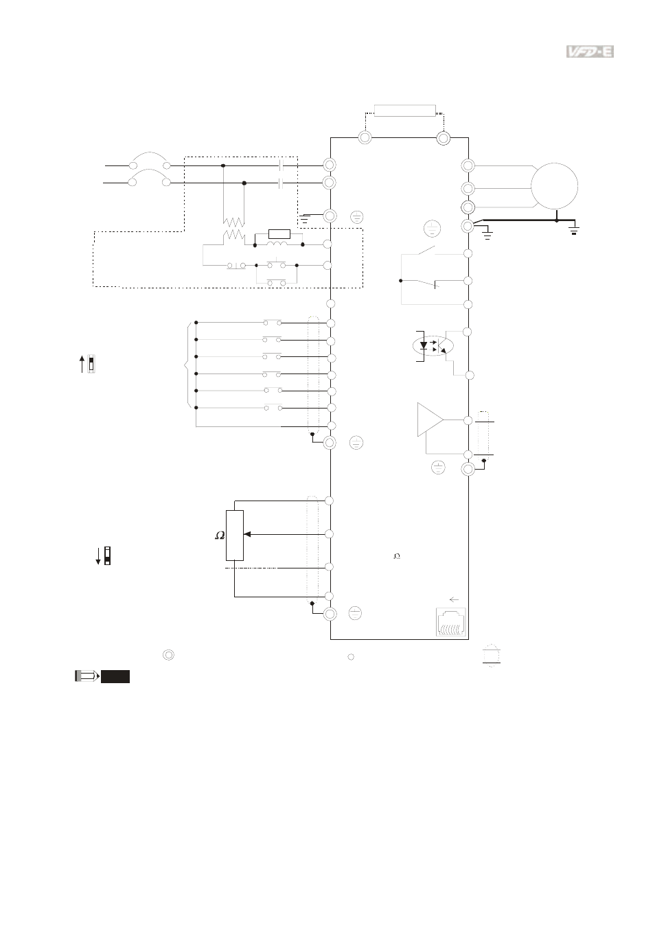
Figure 5 for models of VFD-E Series
VFD002E11T/21T, VFD004E11A/21T, VFD007E21T
AVI
ACI
ACM
B1
+10V
5K
3
2
1
Power supply
+10V 20mA
Master Fr equency
0 to 10V 47K
Analog S ignal Common
E
Main c ircui t (power) terminals
Contr ol c ircuit ter minals
Shielded l eads & Cable
E
R(L1)
S(L2)
F us e/NF B(No F use B reaker)
SA
OF F
ON
MC
MC
RB
RC
Recommended Circuit
when power s uppl y
is turned O FF by a
fault output
R(L1)
S(L2)
E
Analog Multi- func tion
Output Termi nal
factory setti ng: Analog
freq./ cur rent meter
0~ 10V DC/ 2mA
U(T1)
V(T2)
W(T3)
IM
3~
AFM
ACM
RA
RB
RC
Motor
F ac tor y s etting:
Driv e is in operation
48V50mA Max.
Multi-function
Photocoulper O utput
Analog S ignal common
E
E
MO1
MCM
MI1
MI2
MI3
MI4
MI6
MI5
DCM
+24V
F WD/Stop
REV/Stop
Multi-s tep 1
Multi-s tep 2
Multi-s tep 3
Multi-s tep 4
Digital Si gnal Common
F ac tor y
setting
Sw2
AVI
ACI
F act ory set ting :
ACI Mod e
ACI/AVI sw it ch
When switch in g to AVI,
it in dicates AVI2
B2
RS-485
Seri al interface
1: Reserv ed
2: EV
5: SG +
6: Reserv ed
7: Reserv ed
8: Reserv ed
3: G ND
4: SG -
8 1
Sw1
NPN
PNP
F act ory set ting :
NPN Mo de
Please refer to Fig ure 7
fo r w irin g of NPN
mod e and PNP
mod e.
BR
brake resi stor
(opti onal)
Multi-function c ontact output
Refer to c hapter2.4 for detai ls.
F ac tor y s etting is
malfunction indication
F ac tor y s etting: output
frequency
4-20mA/0-10V
NOTE
F or VF D-E- T s eries, the braking resistor can be used by connecting terminals ( B1 and B2) dir ectly. B ut
it c an't connec t DC- BUS i n parallel.