Delta Electronics AC Motor Drive VFD-E User Manual
Page 300
Appendix D How to Use PLC Function|
Revision June 2008, 04EE, SW--PW V1.11/CTL V2.11
D-17
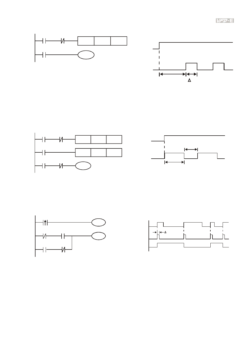
The vibrating circuitry of cycle time ΔT(On)+ΔT(Off):
T0
X0
TMR
Y1
Y1
T0
Kn
Y1
T
T
n
X0
The figure above uses timer T0 to control coil Y1 to be ON. After Y1 is ON, timer T0 will be
closed at the next scan period and output Y1. The oscillating circuit will be shown as above. (n
is the setting of timer and it is decimal number. T is the base of timer. (clock period))
Example 8: Blinking Circuit
T2
TMR
Kn2
T1
X0
TMR
Y1
T2
T1
Kn1
X0
T1
Y1
T
n1
X0
T
n2
*
*
The figure above is common used oscillating circuit for indication light blinks or buzzer alarms. It
uses two timers to control On/OFF time of Y1 coil. If figure, n1 and n2 are timer setting of T1
and T2. T is the base of timer (clock period)
Example 9: Triggered Circuit
Y1
M0
X0
Y1
Y1
M0
M0
X0
M0
Y1
T
In figure above, the rising-edge differential command of X0 will make coil M0 to have a single
pulse of ΔT (a scan time). Y1 will be ON during this scan time. In the next scan time, coil M0
will be OFF, normally close M0 and normally close Y1 are all closed. However, coil Y1 will keep
on being ON and it will make coil Y1 to be OFF once a rising-edge comes after input X0 and coil
M0 is ON for a scan time. The timing chart is as shown above. This circuit usually executes
alternate two actions with an input. From above timing: when input X0 is a square wave of a
period T, output coil Y1 is square wave of a period 2T.