Delta Electronics AC Motor Drive VFD-E User Manual
Page 293
Appendix D How to Use PLC Function|
D-10
Revision June 2008, 04EE, SW--PW V1.11/CTL V2.11
16-bit binary number, i.e. a word, in each register. It uses two continuous number
of data register to store double words.
Equipment indication: D0, D1,…,D29. The symbol of equipment is D and
the number uses decimal.
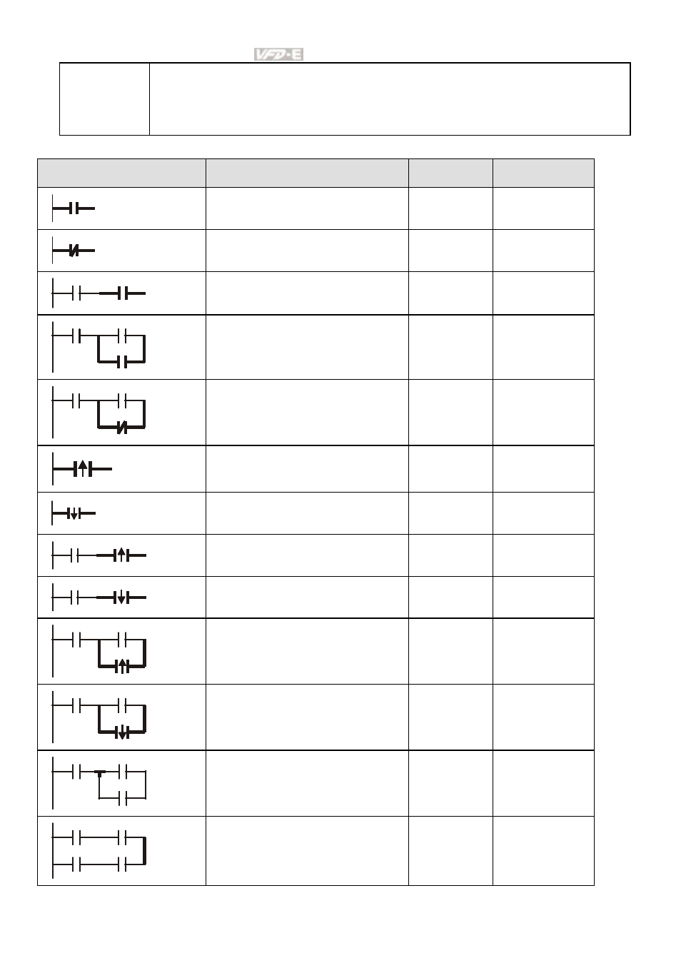
The structure and explanation of ladder diagram:
Ladder Diagram Structure
Explanation
Command
Equipment
Normally open, contact a
LD
X, Y, M, T, C
Normally closed, contact b
LDI
X, Y, M, T, C
Serial normally open
AND
X, Y, M, T, C
Parallel normally open
OR
X, Y, M, T, C
Parallel normally closed
ORI
X, Y, M, T, C
Rising-edge trigger switch
LDP
X, Y, M, T, C
Falling-edge trigger switch
LDF
X, Y, M, T, C
Rising-edge trigger in serial
ANDP
X, Y, M, T, C
Falling-edge trigger in serial
ANDF
X, Y, M, T, C
Rising-edge trigger in parallel
ORP
X, Y, M, T, C
Falling-edge trigger in parallel
ORF
X, Y, M, T, C
Block in serial
ANB
none
Block in parallel
ORB
none
- AC Motor Drive VFD-G (183 pages)
- SMT Power Inductor SIL104R (1 page)
- Q48SB (2 pages)
- Planar DC/DC Transformer ER/ER(Plate) 22 (1 page)
- SMT Power Inductor HCB1190B (1 page)
- Series E48SR (15 pages)
- E48SR12007 (15 pages)
- SMT Power Inductor SIWC1360 (1 page)
- PFC Chokes PFC2815V Series (1 page)
- SMT Power Inductor SIB86 (1 page)
- PMC-24V050W1AA (2 pages)
- SMT Power Inductor HCB1050 (1 page)
- SMT Power Inductor HAH1330 (1 page)
- PFC Chokes PFC4120V Series (1 page)
- PFC Choke PFC3520V Series (1 page)
- SMT Power Inductor HCB1047B (1 page)
- SMT Power Inductor HAH1365 (1 page)
- SMT Power Inductor HMS1355 (1 page)
- Series S48SA (13 pages)
- E48SC (2 pages)
- SMT Power Inductor SILM106 (1 page)
- Delphi Series L48DB (2 pages)
- S48SA (13 pages)
- E36SR (2 pages)
- 3KVA (31 pages)
- SMT Power Inductor HMU1056L (1 page)
- Through Hole Power Inductors THCBR1090 (1 page)
- SMT Power Inductor SIL625 (1 page)
- SMT Power Inductor 1378(S) (1 page)
- Through Hole Power Inductors 1411 (1 page)
- Current Sense Transformers TCE1310H (1 page)
- H48SR (13 pages)
- Series E48SH (15 pages)
- AC Motor Drive VFD-EL (209 pages)
- Through Hole Power Inductors THAH1095 (1 page)
- Suppression Inductors LFU09V (1 page)
- SMT Power Inductor HCB0740A (1 page)
- Power Output Module DVPPS01 (2 pages)
- SMT Power Inductor SIR74 (1 page)
- L36SA (2 pages)
- 4.5V~ 5.5V (3 pages)
- Delphi Series V48SB (2 pages)
- Series S48SP (14 pages)
- Series 240W (11 pages)
- Delphi Series E24SR (15 pages)