Delta Electronics AC Motor Drive VFD-E User Manual
Page 197
Chapter 4 Parameters|
4-144
Revision June 2008, 04EE, SW--PW V1.11/CTL V2.11
Group 12: Analog Input/Output Parameters for Extension Card
Make sure that the extension card is installed on the AC motor drive correctly before using group 12
parameters. See Appendix B for details.
12.00
AI1 Function Selection
Factory Setting: 0
Settings
0
Disabled
1
Source of the 1st frequency
2
Source of the 2nd frequency
3
PID Set Point (PID enable)
4
Positive
PID
feedback
5
Negative
PID
feedback
12.01
AI1 Analog Signal Mode
Factory Setting: 1
Settings
0
ACI2 analog current (0.0 ~ 20.0mA)
1
AVI3 analog voltage (0.0 ~ 10.0V)
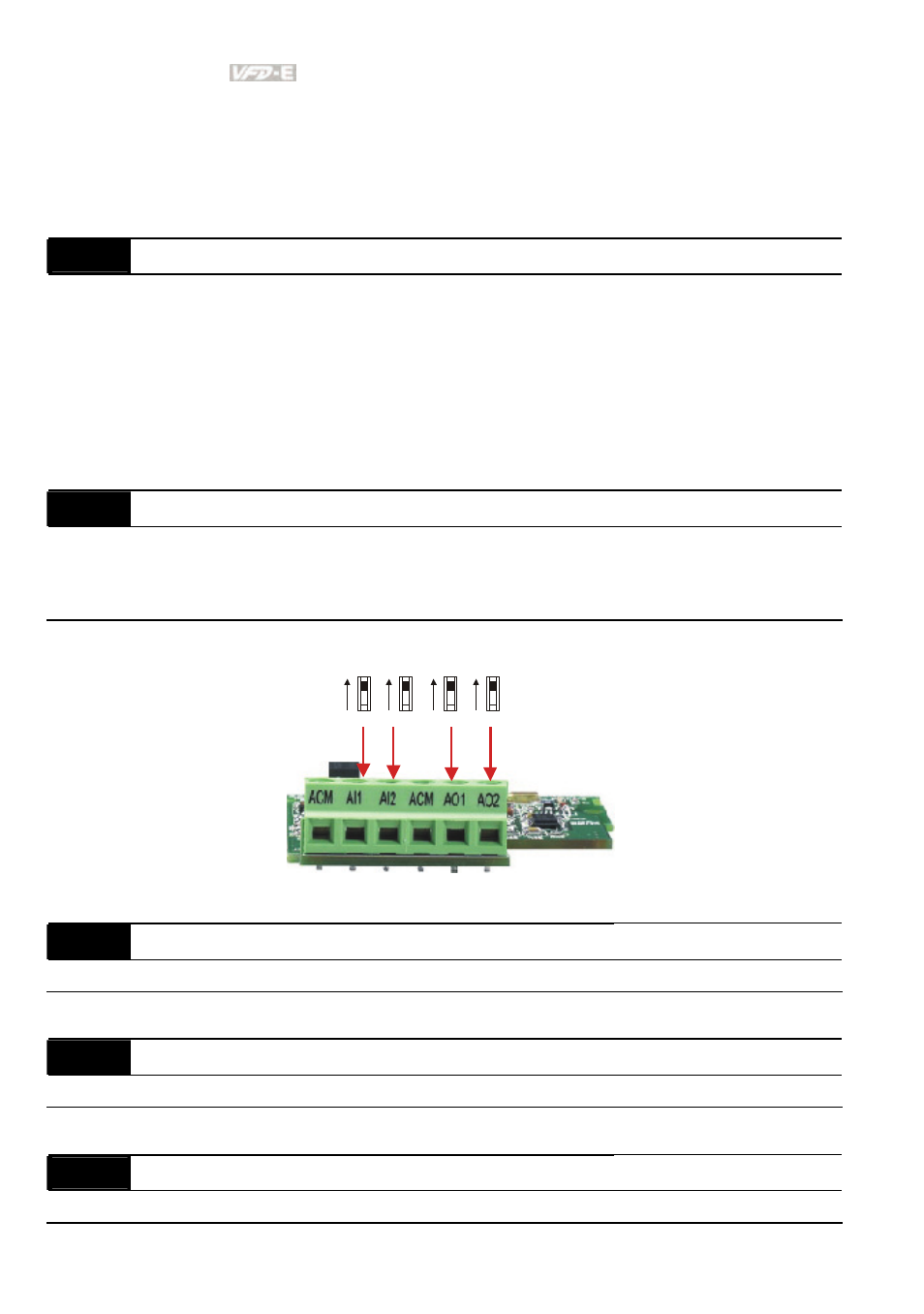
Besides parameters settings, the voltage/current mode should be used with the switch.
AVI3
ACI2
AVI4
ACI3
AVO1
ACO1
AVO2
ACO2
12.02
Min. AVI3 Input Voltage
Unit: 0.1
Settings
0.0 to 10.0V
Factory Setting: 0.0
12.03
Min. AVI3 Scale Percentage
Unit: 0.1
Settings
0.0 to 100.0%
Factory Setting: 0.0
12.04
Max. AVI3 Input Voltage
Unit: 0.1
Settings
0.0 to 10.0V
Factory Setting: 10.0
- AC Motor Drive VFD-G (183 pages)
- SMT Power Inductor SIL104R (1 page)
- Q48SB (2 pages)
- Planar DC/DC Transformer ER/ER(Plate) 22 (1 page)
- SMT Power Inductor HCB1190B (1 page)
- Series E48SR (15 pages)
- E48SR12007 (15 pages)
- SMT Power Inductor SIWC1360 (1 page)
- PFC Chokes PFC2815V Series (1 page)
- SMT Power Inductor SIB86 (1 page)
- PMC-24V050W1AA (2 pages)
- SMT Power Inductor HCB1050 (1 page)
- SMT Power Inductor HAH1330 (1 page)
- PFC Chokes PFC4120V Series (1 page)
- PFC Choke PFC3520V Series (1 page)
- SMT Power Inductor HCB1047B (1 page)
- SMT Power Inductor HAH1365 (1 page)
- SMT Power Inductor HMS1355 (1 page)
- Series S48SA (13 pages)
- E48SC (2 pages)
- SMT Power Inductor SILM106 (1 page)
- Delphi Series L48DB (2 pages)
- S48SA (13 pages)
- E36SR (2 pages)
- 3KVA (31 pages)
- SMT Power Inductor HMU1056L (1 page)
- Through Hole Power Inductors THCBR1090 (1 page)
- SMT Power Inductor SIL625 (1 page)
- SMT Power Inductor 1378(S) (1 page)
- Through Hole Power Inductors 1411 (1 page)
- Current Sense Transformers TCE1310H (1 page)
- H48SR (13 pages)
- Series E48SH (15 pages)
- AC Motor Drive VFD-EL (209 pages)
- Through Hole Power Inductors THAH1095 (1 page)
- Suppression Inductors LFU09V (1 page)
- SMT Power Inductor HCB0740A (1 page)
- Power Output Module DVPPS01 (2 pages)
- SMT Power Inductor SIR74 (1 page)
- L36SA (2 pages)
- 4.5V~ 5.5V (3 pages)
- Delphi Series V48SB (2 pages)
- Series S48SP (14 pages)
- Series 240W (11 pages)
- Delphi Series E24SR (15 pages)