Delta Electronics AC Motor Drive VFD-E User Manual
Page 123
Chapter 4 Parameters|
4-70
Revision June 2008, 04EE, SW--PW V1.11/CTL V2.11
60Hz
0Hz 0V
5V
10V
Pr.01.00=60Hz--Max. output Freq.
Potentiometer
Pr.04.00 =16.7%--Bias adjustment
Pr.04.01 =0--Positive bias
Pr.04.02 =100%--Input gain
Pr.04.03 =0--No negative bias command
Gain:100%
Bias adjustment:((10Hz/60Hz)/(Gain/100%))*100%=16.7%
10Hz
Bias
Adjustment
40Hz
Example 3: Use of bias and gain for use of full range
This example also shows a popular method. The whole scale of the potentiometer can be used as
desired. In addition to signals of 0 to 10V, the popular voltage signals also include signals of 0 to 5V,
or any value under 10V. Regarding the setting, please refer to the following examples.
60Hz
0Hz
0V
5V
10V
Pr.01.00=60Hz--Max. output Freq.
Potentiometer
Pr.04.00 =20.0%--Bias adjustment
Pr.04.01 =0--Positive bias
Pr.04.02 =83.3%--Input gain
Pr.04.03 =0--No negative bias command
Gain:(10V/(10V+2V))*100%=83.3%
Bias adjustment:((10Hz/60Hz)/(Gain/100%))*100%=20.0%
10Hz
Bias
Adjustment
-2V
XV
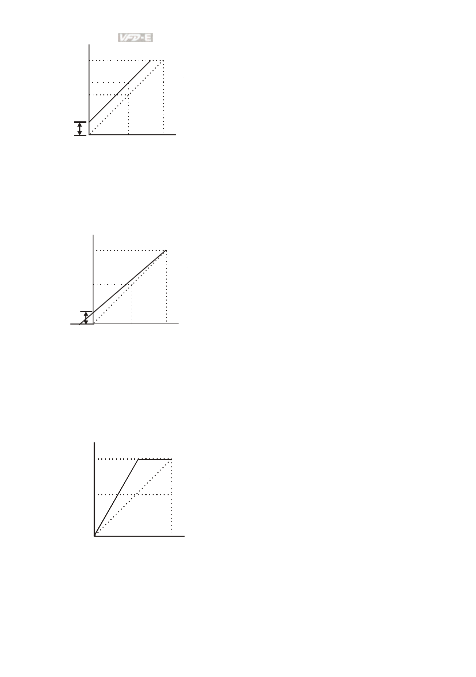
Example 4: Use of 0-5V potentiometer range via gain adjustment
This example shows a potentiometer range of 0 to 5 Volts. Instead of adjusting gain as example
below, you can set Pr. 01.00 to 120Hz to achieve the same results.
Pr.01.00=60Hz--Max. output Freq.
Potentiometer
Pr.04.00 =0.0%--Bias adjustment
Pr.04.01 =0--Positive bias
Pr.04.02 =200%--Input gain
Pr.04.03 =0--No negative bias command
Gain:(10V/5V)*100%=200%
60Hz
0Hz 0V
5V
30Hz
Gain
adjustment
10V