Delta Electronics AC Motor Drive VFD-E User Manual
Page 321
Appendix D How to Use PLC Function|
D-38
Revision June 2008, 04EE, SW--PW V1.11/CTL V2.11
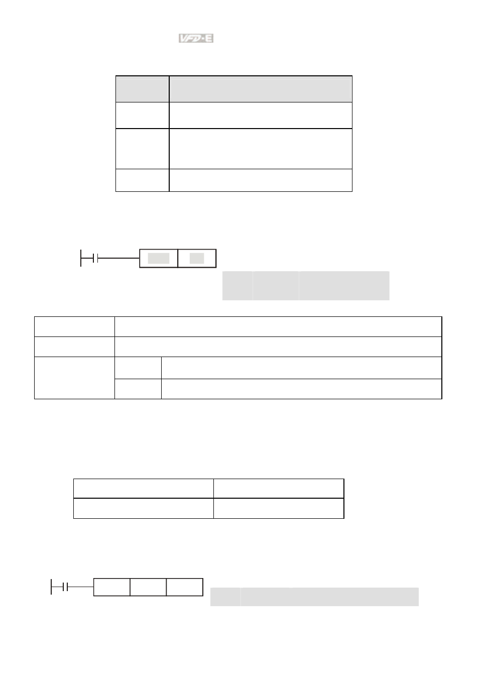
Explanations:
When the RST command is driven, motion of its specific device is as follows:
Device
Status
Y, M
Coil and contact will be set to “OFF”.
T, C
Present values of the timer or counter
will be set to 0, and the coil and contact
will be set to “OFF.”
D
The content value will be set to 0.
Program Example:
Ladder diagram:
Command code: Operation:
LD
X0
Load contact A of X0
X0
Y5
RST
RST
Y5
Clear contact Y5
Mnemonic Function
TMR 16-bit
timer
T-K T0~T15,
K0~K32,767
Operand
T-D T0~T15,
D0~D29
Explanations:
When TMR command is executed, the specific coil of timer is ON and timer will start to count. When
the setting value of timer is attained (counting value >= setting value), the contact will be as following:
NO(Normally Open) contact
Open collector
NC(Normally Closed) contact
Close collector
Program Example:
Ladder diagram:
Command code: Operation:
LD
X0
Load contact A of X0 T5 timer
X0
T5
TMR
K1000
TMR
T5 K1000 Setting is K1000
- AC Motor Drive VFD-G (183 pages)
- SMT Power Inductor SIL104R (1 page)
- Q48SB (2 pages)
- Planar DC/DC Transformer ER/ER(Plate) 22 (1 page)
- SMT Power Inductor HCB1190B (1 page)
- Series E48SR (15 pages)
- E48SR12007 (15 pages)
- SMT Power Inductor SIWC1360 (1 page)
- PFC Chokes PFC2815V Series (1 page)
- SMT Power Inductor SIB86 (1 page)
- PMC-24V050W1AA (2 pages)
- SMT Power Inductor HCB1050 (1 page)
- SMT Power Inductor HAH1330 (1 page)
- PFC Chokes PFC4120V Series (1 page)
- PFC Choke PFC3520V Series (1 page)
- SMT Power Inductor HCB1047B (1 page)
- SMT Power Inductor HAH1365 (1 page)
- SMT Power Inductor HMS1355 (1 page)
- Series S48SA (13 pages)
- E48SC (2 pages)
- SMT Power Inductor SILM106 (1 page)
- Delphi Series L48DB (2 pages)
- S48SA (13 pages)
- E36SR (2 pages)
- 3KVA (31 pages)
- SMT Power Inductor HMU1056L (1 page)
- Through Hole Power Inductors THCBR1090 (1 page)
- SMT Power Inductor SIL625 (1 page)
- SMT Power Inductor 1378(S) (1 page)
- Through Hole Power Inductors 1411 (1 page)
- Current Sense Transformers TCE1310H (1 page)
- H48SR (13 pages)
- Series E48SH (15 pages)
- AC Motor Drive VFD-EL (209 pages)
- Through Hole Power Inductors THAH1095 (1 page)
- Suppression Inductors LFU09V (1 page)
- SMT Power Inductor HCB0740A (1 page)
- Power Output Module DVPPS01 (2 pages)
- SMT Power Inductor SIR74 (1 page)
- L36SA (2 pages)
- 4.5V~ 5.5V (3 pages)
- Delphi Series V48SB (2 pages)
- Series S48SP (14 pages)
- Series 240W (11 pages)
- Delphi Series E24SR (15 pages)