D.4.7 register types – Delta Electronics AC Motor Drive VFD-E User Manual
Page 307
Appendix D How to Use PLC Function|
D-24
Revision June 2008, 04EE, SW--PW V1.11/CTL V2.11
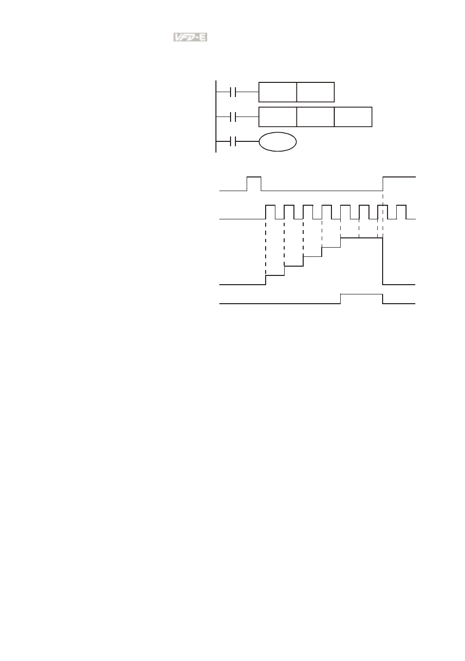
Example:
LD X0
RST C0
LD X1
CNT C0 K5
LD C0
OUT Y0
C0
Y0
X1
C0
K5
CNT
X0
C0
RST
1. When X0=On, RST command is
executed, C0 reset to 0 and
output contact reset to Off.
2. When X1 is from Off to On,
counter will count up (add 1).
3. When counter C0 attains settings
K5, C0 contact is On and C0 =
setting =K5. C0 won’t accept X1
trigger signal and C0 remains
K5.
X0
X1
0
1
2
3
4
5
0
Contacts Y0, C0
C0
present
value
settings
32-bit high-speed addition/subtraction counter C235:
1.
Setting range of 32-bit high-speed addition/subtraction counter is :
K-2,147,483,648~K2,147,483,647.
2.
The settings can be positive / negative numbers by using constant K or data register D
(special data register D1000~D1044 is not included). If using data register D, the setting
will occupy two continuous data register.
The total band width of high-speed counter that VFD-E supports is up to 30kHz and 500kHz for pulse
input.
D.4.7 Register Types
There are two types of register which sorts by characters in the following:
1. General
register
: The data in register will be cleared to 0 when PLC switches from RUN
to STOP or power is off.
2. Special
register
: Each special register has the special definition and purpose. It is used
to save system status, error messages, monitor state.