Delta Electronics AC Motor Drive VFD-E User Manual
Page 323
Appendix D How to Use PLC Function|
D-40
Revision June 2008, 04EE, SW--PW V1.11/CTL V2.11
Counter
The coil is OFF, and the counting value and the contact stay at
their present condition
Coils driven up by the OUT
command
All turned OFF
Devices driven up by the
SET and RST commands
Stay at present condition
Application commands
All of them are not acted , but the nest loop FOR-NEXT
command will still be executed for times defined by users even
though the MC-MCR commands is OFF.
2.
MCR is the main-control ending command that is placed at the end of the main-control
program and there should not be any contact commands prior to the MCR command.
3.
Commands of the MC-MCR main-control program supports the nest program structure,
with 8 layers as its greatest. Please use the commands in order from N0~ N7, and refer to
the following:
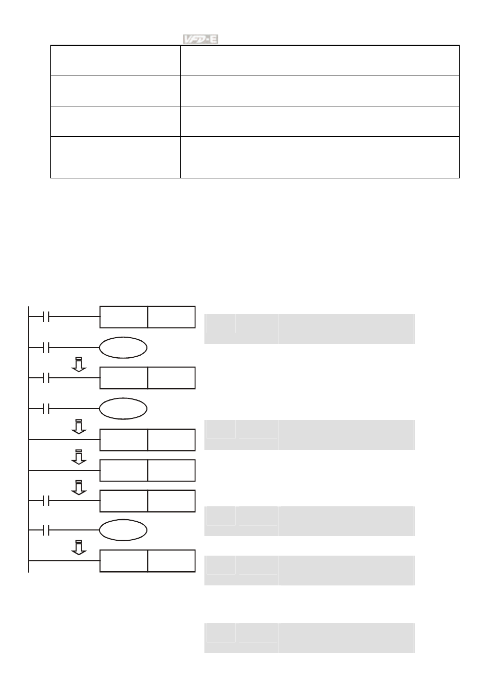
Program Example:
Ladder diagram:
Command code: Operation:
LD
X0
Load A contact of X0
MC
N0
Enable N0 common series
connection contact
LD
X1
Load A contact of X1
OUT
Y0
Drive Y0 coil
:
LD
X2
Load A contact of X2
MC
N1
Enable N1 common series
connection contact
LD
X3
Load A contact of X3
OUT
Y1
Drive Y1 coil
:
MCR
N1
Disable N1 common series
connection contact
:
MCR
N0
Disable N0 common series
connection contact
:
LD
X10
Load A contact of X10
X0
Y0
MC
N0
X1
X2
Y1
MC
N1
X3
MCR
N1
MCR
N0
X10
MC
N0
Y10
X11
MCR
N0
MC
N0
Enable N0 common series
connection contact