Delta Electronics AC Motor Drive VFD-E User Manual
Page 298
Appendix D How to Use PLC Function|
Revision June 2008, 04EE, SW--PW V1.11/CTL V2.11
D-15
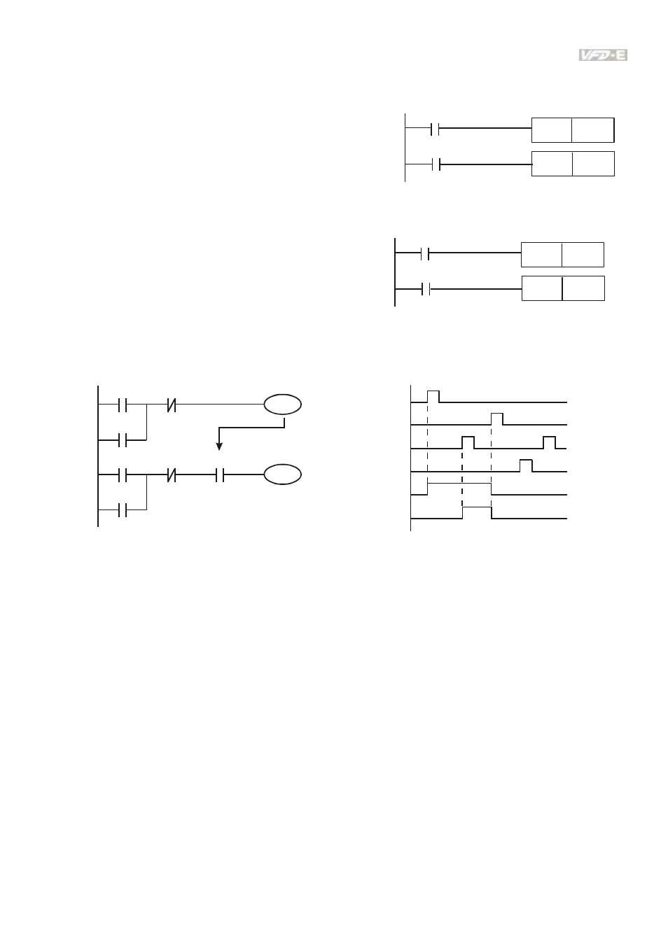
Example 3: the latching circuit of SET and RST commands
SET
Y1
RST
Y1
X1
X2
Top priority of stop
The figure at the right side is latching circuit that made
up of RST and SET command.
It is top priority of stop when RST command is set
behind SET command. When executing PLC from up
to down, The coil Y1 is ON and coil Y1 will be OFF
when X1 and X2 act at the same time, therefore it calls
priority of stop.
It is top priority of start when SET command is set after
RST command. When X1 and X2 act at the same
time, Y1 is ON so it calls top priority of start.
SET
Y1
RST
Y1
X2
X1
Top priority of start
The common control circuit
Example 4: condition control
X3
Y1
X1
Y1
X4
Y2
X2
Y2
Y1
X1
X3
X2
X4
Y1
Y2
X1 and X3 can start/stop Y1 separately, X2 and X4 can start/stop Y2 separately and they are all
self latched circuit. Y1 is an element for Y2 to do AND function due to the normally open contact
connects to Y2 in series. Therefore, Y1 is the input of Y2 and Y2 is also the input of Y1.
- AC Motor Drive VFD-G (183 pages)
- SMT Power Inductor SIL104R (1 page)
- Q48SB (2 pages)
- Planar DC/DC Transformer ER/ER(Plate) 22 (1 page)
- SMT Power Inductor HCB1190B (1 page)
- Series E48SR (15 pages)
- E48SR12007 (15 pages)
- SMT Power Inductor SIWC1360 (1 page)
- PFC Chokes PFC2815V Series (1 page)
- SMT Power Inductor SIB86 (1 page)
- PMC-24V050W1AA (2 pages)
- SMT Power Inductor HCB1050 (1 page)
- SMT Power Inductor HAH1330 (1 page)
- PFC Chokes PFC4120V Series (1 page)
- PFC Choke PFC3520V Series (1 page)
- SMT Power Inductor HCB1047B (1 page)
- SMT Power Inductor HAH1365 (1 page)
- SMT Power Inductor HMS1355 (1 page)
- Series S48SA (13 pages)
- E48SC (2 pages)
- SMT Power Inductor SILM106 (1 page)
- Delphi Series L48DB (2 pages)
- S48SA (13 pages)
- E36SR (2 pages)
- 3KVA (31 pages)
- SMT Power Inductor HMU1056L (1 page)
- Through Hole Power Inductors THCBR1090 (1 page)
- SMT Power Inductor SIL625 (1 page)
- SMT Power Inductor 1378(S) (1 page)
- Through Hole Power Inductors 1411 (1 page)
- Current Sense Transformers TCE1310H (1 page)
- H48SR (13 pages)
- Series E48SH (15 pages)
- AC Motor Drive VFD-EL (209 pages)
- Through Hole Power Inductors THAH1095 (1 page)
- Suppression Inductors LFU09V (1 page)
- SMT Power Inductor HCB0740A (1 page)
- Power Output Module DVPPS01 (2 pages)
- SMT Power Inductor SIR74 (1 page)
- L36SA (2 pages)
- 4.5V~ 5.5V (3 pages)
- Delphi Series V48SB (2 pages)
- Series S48SP (14 pages)
- Series 240W (11 pages)
- Delphi Series E24SR (15 pages)