Delta Electronics AC Motor Drive VFD-E User Manual
Page 136
Chapter 4 Parameters|
Revision June 2008, 04EE, SW--PW V1.11/CTL V2.11
4-83
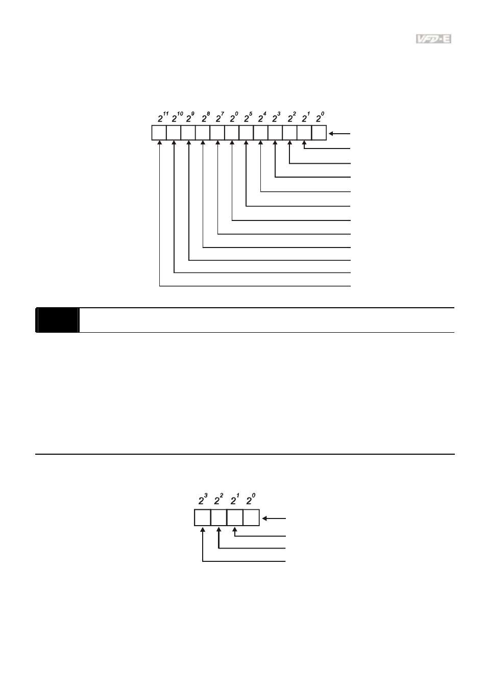
When extension card is installed, the number of the digital input terminals will increase
according to the extension card. The maximum number of the digital input terminals is shown
as follows.
1
2
3
4
5
0
MI1
MI2
MI3
MI4
MI5
MI6
Weights
Bit
7
8
9
10
11
6
MI7
MI8
MI9
MI10
MI11
MI12
0=not used
1=Used by PLC
04.25
The Analog Input Used by PLC (NOT for VFD*E*C models)
Settings
Read Only
Factory setting: ##
Display
Bit0=1: AVI used by PLC
Bit1=1: ACI/AVI2 used by PLC
Bit2=1: AI1 used by PLC
Bit3=1: AI2 used by PLC
The equivalent 2-bit is used to display the status(used or not used) of each analog input. The
value for Pr.04.25 to display is the result after converting 2-bit binary into decimal value.
1 0
Weights
Bit
0=not used
1=used by PLC
AVI
ACI/AVI2
1
3
2
AI1 (optional)
AI2 (optional)
- AC Motor Drive VFD-G (183 pages)
- SMT Power Inductor SIL104R (1 page)
- Q48SB (2 pages)
- Planar DC/DC Transformer ER/ER(Plate) 22 (1 page)
- SMT Power Inductor HCB1190B (1 page)
- Series E48SR (15 pages)
- E48SR12007 (15 pages)
- SMT Power Inductor SIWC1360 (1 page)
- PFC Chokes PFC2815V Series (1 page)
- SMT Power Inductor SIB86 (1 page)
- PMC-24V050W1AA (2 pages)
- SMT Power Inductor HCB1050 (1 page)
- SMT Power Inductor HAH1330 (1 page)
- PFC Chokes PFC4120V Series (1 page)
- PFC Choke PFC3520V Series (1 page)
- SMT Power Inductor HCB1047B (1 page)
- SMT Power Inductor HAH1365 (1 page)
- SMT Power Inductor HMS1355 (1 page)
- Series S48SA (13 pages)
- E48SC (2 pages)
- SMT Power Inductor SILM106 (1 page)
- Delphi Series L48DB (2 pages)
- S48SA (13 pages)
- E36SR (2 pages)
- 3KVA (31 pages)
- SMT Power Inductor HMU1056L (1 page)
- Through Hole Power Inductors THCBR1090 (1 page)
- SMT Power Inductor SIL625 (1 page)
- SMT Power Inductor 1378(S) (1 page)
- Through Hole Power Inductors 1411 (1 page)
- Current Sense Transformers TCE1310H (1 page)
- H48SR (13 pages)
- Series E48SH (15 pages)
- AC Motor Drive VFD-EL (209 pages)
- Through Hole Power Inductors THAH1095 (1 page)
- Suppression Inductors LFU09V (1 page)
- SMT Power Inductor HCB0740A (1 page)
- Power Output Module DVPPS01 (2 pages)
- SMT Power Inductor SIR74 (1 page)
- L36SA (2 pages)
- 4.5V~ 5.5V (3 pages)
- Delphi Series V48SB (2 pages)
- Series S48SP (14 pages)
- Series 240W (11 pages)
- Delphi Series E24SR (15 pages)