Delta Electronics AC Motor Drive VFD-E User Manual
Page 299
Appendix D How to Use PLC Function|
D-16
Revision June 2008, 04EE, SW--PW V1.11/CTL V2.11
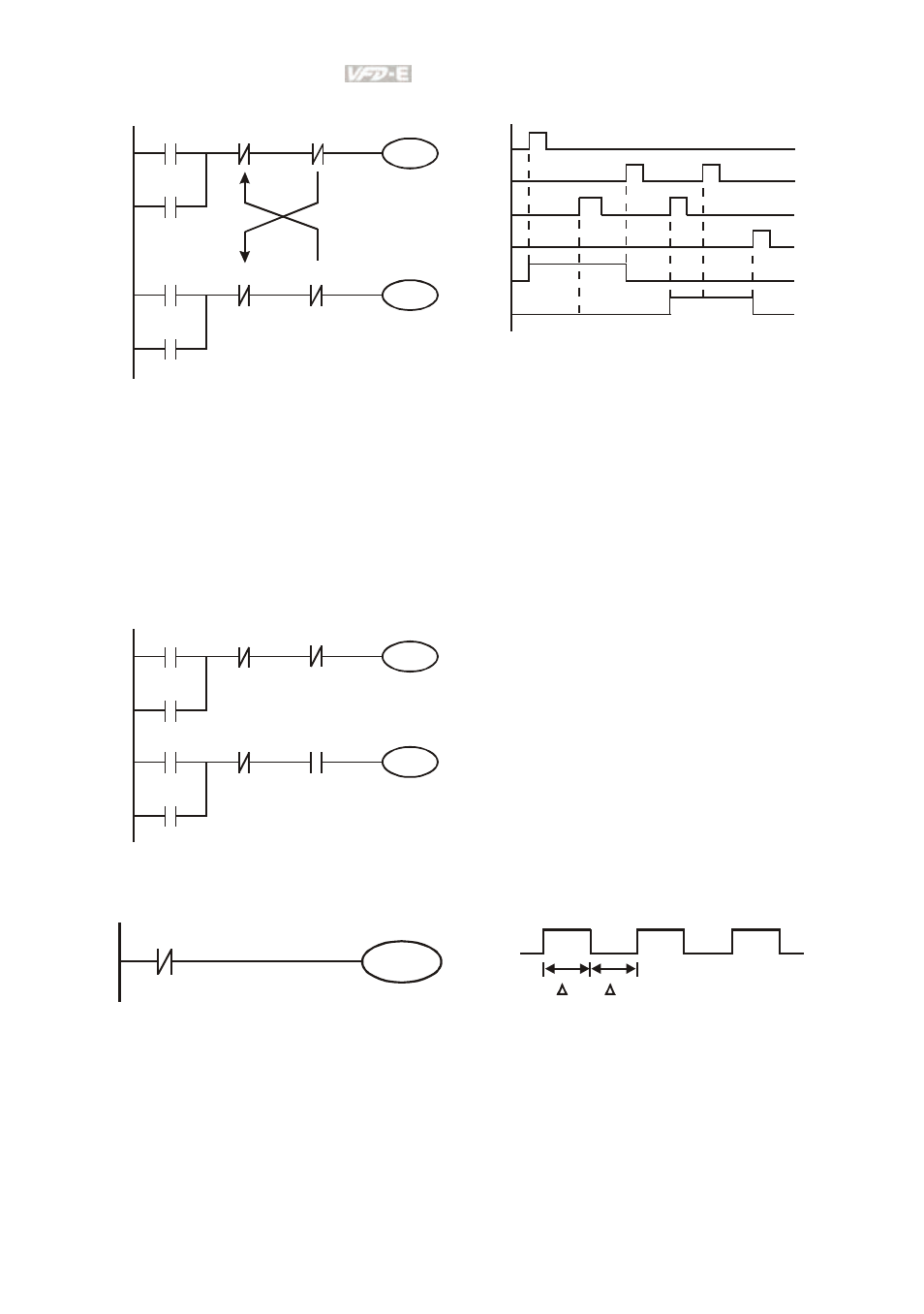
Example 5: Interlock control
X3
Y1
X1
Y1
X4
Y2
X2
Y2
Y1
Y2
X1
X3
X2
X4
Y1
Y2
The figure above is the circuit of interlock control. Y1 and Y2 will act according to the start
contact X1 and X2. Y1 and Y2 will act not at the same time, once one of them acts and the
other won’t act. (This is called interlock.) Even if X1 and X2 are valid at the same time, Y1 and
Y2 won’t act at the same time due to up-to-down scan of ladder diagram. For this ladder
diagram, Y1 has higher priority than Y2.
Example 6: Sequential Control
X3
Y1
X1
Y1
X4
Y2
X2
Y2
Y1
Y2
If add normally close contact Y2 into Y1
circuit to be an input for Y1 to do AND
function. (as shown in the left side) Y1 is an
input of Y2 and Y2 can stop Y1 after acting.
In this way, Y1 and Y2 can execute in
sequential.
Example 7: Oscillating Circuit
The period of oscillating circuit is ΔT+ΔT
Y1
Y1
Y1
T
T
The figure above is a very simple ladder step diagram. When starting to scan Y1 normally
close contact, Y1 normally close contact is close due to the coil Y1 is OFF. Then it will scan
Y1 and the coil Y1 will be ON and output 1. In the next scan period to scan normally close
contact Y1, Y1 normally close contact will be open due to Y1 is ON. Finally, coil Y1 will be
OFF. The result of repeated scan, coil Y will output the vibrating pulse with cycle timeΔ
T(On)+ΔT(Off).