B.7.3 operation flow chart – Delta Electronics AC Motor Drive VFD-E User Manual
Page 254
Appendix B Accessories|
Revision June 2008, 04EE, SW--PW V1.11/CTL V2.11
B-17
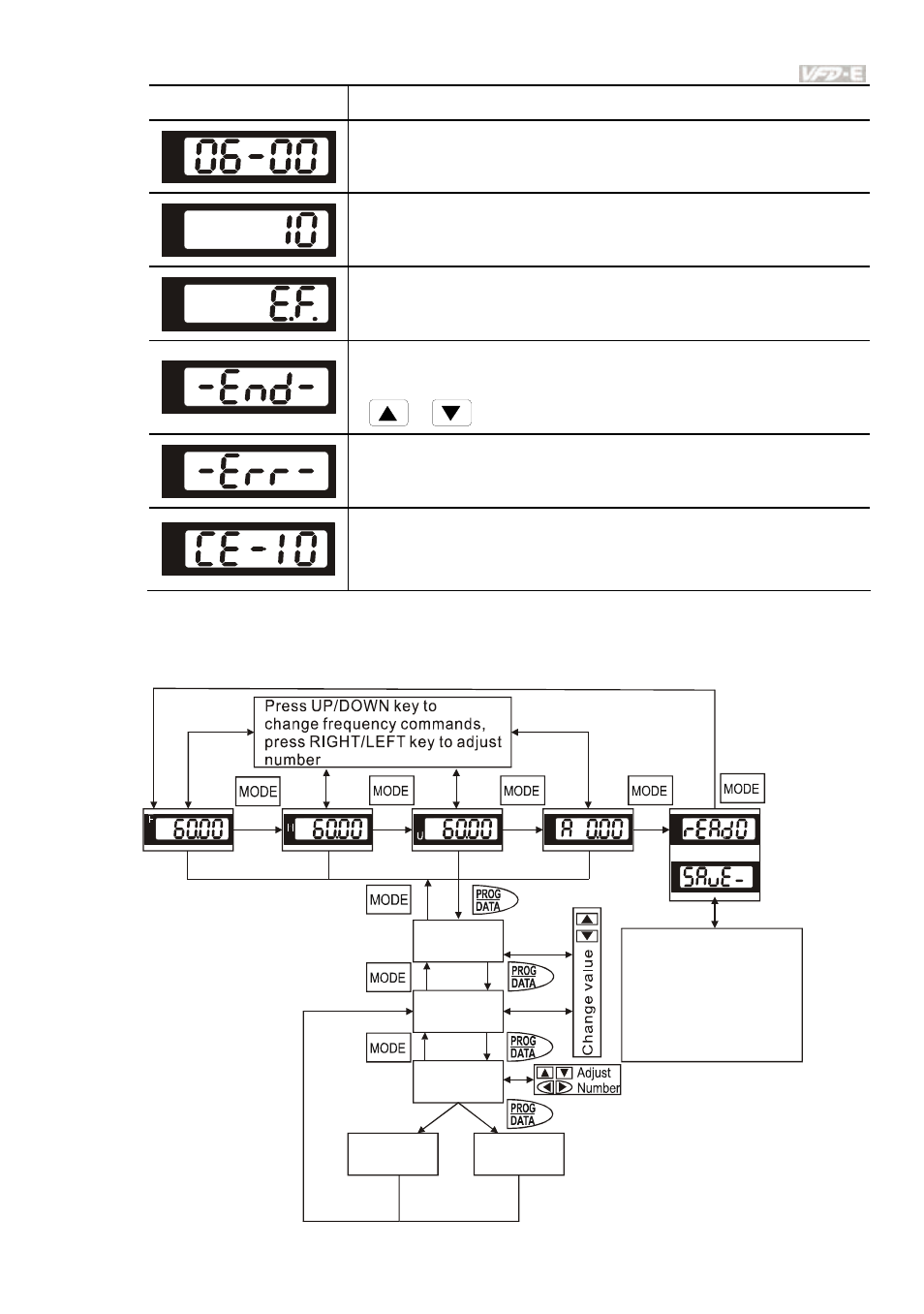
Display Message
Descriptions
The specified parameter setting.
The actual value stored in the specified parameter.
External Fault
“End” displays for approximately 1 second if the entered input data have
been accepted. After a parameter value has been set, the new value is
automatically stored in memory. To modify an entry, use the
or
keys.
“Err” displays if the input is invalid.
Communication Error. Please check the AC motor drive user manual
(Chapter 5, Group 9 Communication Parameter) for more details.
B.7.3 Operation Flow Chart
XX
XX-XX
XXXXX
-END-
VFD-PU06 Operation Flow Chart
Cannot
write in
-ERR-
Or
Succeed to
Write in
Press UP key to select
SAVE or READ.
Press PROG/DATA for
about 2 seconds or until
it is flashing, then save
parameters
or read parameters
.
from PU06 to
AC drive
from AC drive to PU06
- AC Motor Drive VFD-G (183 pages)
- SMT Power Inductor SIL104R (1 page)
- Q48SB (2 pages)
- Planar DC/DC Transformer ER/ER(Plate) 22 (1 page)
- SMT Power Inductor HCB1190B (1 page)
- Series E48SR (15 pages)
- E48SR12007 (15 pages)
- SMT Power Inductor SIWC1360 (1 page)
- PFC Chokes PFC2815V Series (1 page)
- SMT Power Inductor SIB86 (1 page)
- PMC-24V050W1AA (2 pages)
- SMT Power Inductor HCB1050 (1 page)
- SMT Power Inductor HAH1330 (1 page)
- PFC Chokes PFC4120V Series (1 page)
- PFC Choke PFC3520V Series (1 page)
- SMT Power Inductor HCB1047B (1 page)
- SMT Power Inductor HAH1365 (1 page)
- SMT Power Inductor HMS1355 (1 page)
- Series S48SA (13 pages)
- E48SC (2 pages)
- SMT Power Inductor SILM106 (1 page)
- Delphi Series L48DB (2 pages)
- S48SA (13 pages)
- E36SR (2 pages)
- 3KVA (31 pages)
- SMT Power Inductor HMU1056L (1 page)
- Through Hole Power Inductors THCBR1090 (1 page)
- SMT Power Inductor SIL625 (1 page)
- SMT Power Inductor 1378(S) (1 page)
- Through Hole Power Inductors 1411 (1 page)
- Current Sense Transformers TCE1310H (1 page)
- H48SR (13 pages)
- Series E48SH (15 pages)
- AC Motor Drive VFD-EL (209 pages)
- Through Hole Power Inductors THAH1095 (1 page)
- Suppression Inductors LFU09V (1 page)
- SMT Power Inductor HCB0740A (1 page)
- Power Output Module DVPPS01 (2 pages)
- SMT Power Inductor SIR74 (1 page)
- L36SA (2 pages)
- 4.5V~ 5.5V (3 pages)
- Delphi Series V48SB (2 pages)
- Series S48SP (14 pages)
- Series 240W (11 pages)
- Delphi Series E24SR (15 pages)