Delta Electronics AC Motor Drive VFD-E User Manual
Page 301
Appendix D How to Use PLC Function|
D-18
Revision June 2008, 04EE, SW--PW V1.11/CTL V2.11
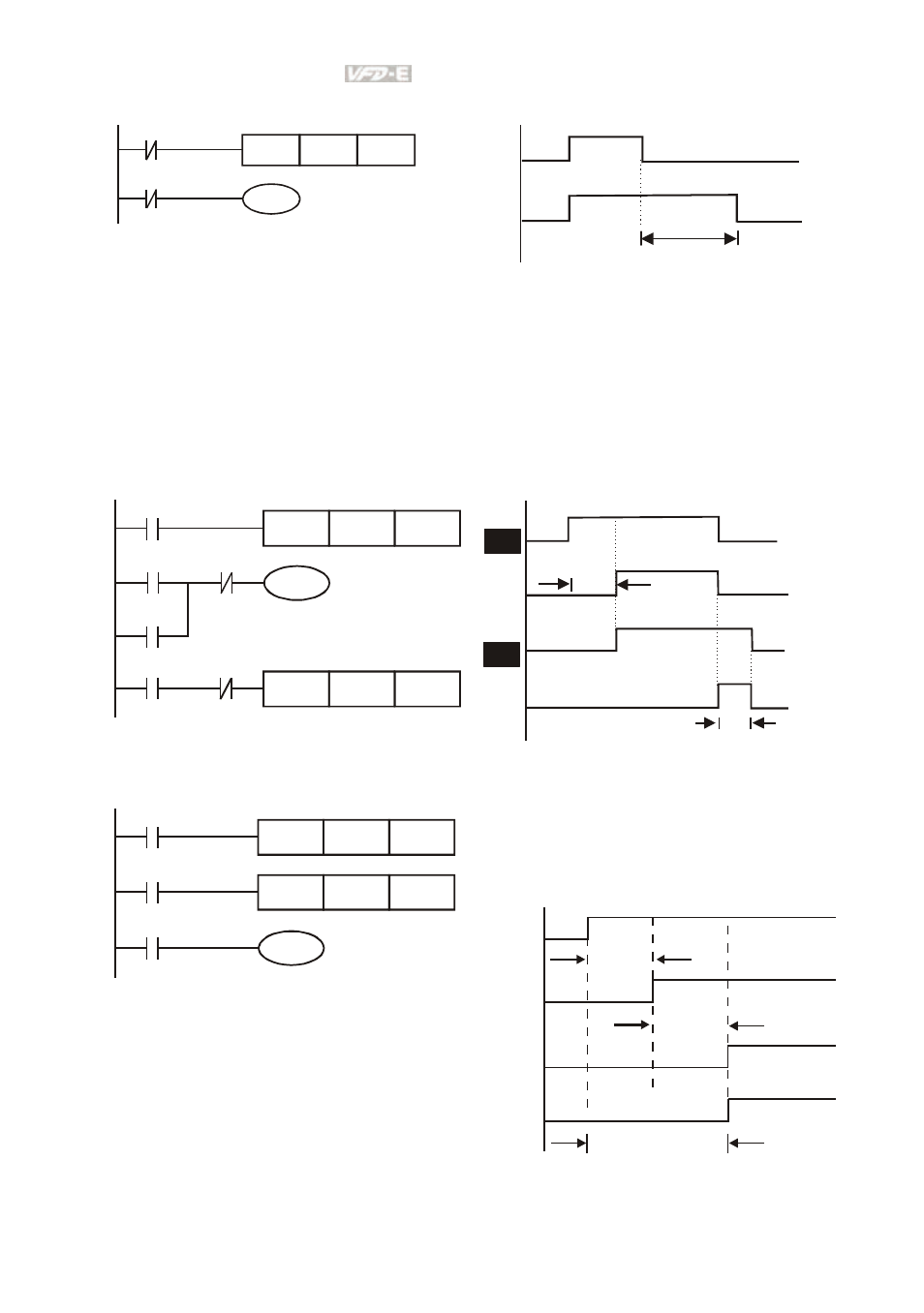
Example 10: Delay Circuit
T10
X0
TMR
Y1
T10
K1000
TB = 0.1 sec
X0
Y1
100 seconds
When input X0 is ON, output coil Y1 will be ON at the same time due to the corresponding
normally close contact OFF makes timer T10 to be OFF. Output coil Y1 will be OFF after
delaying 100 seconds (K1000*0.1 seconds =100 seconds) once input X0 is OFF and T10 is
ON. Please refer to timing chart above.
Example 11: Output delay circuit, in the following example, the circuit is made up of two timers. No
matter input X0 is ON or OFF, output Y4 will be delay.
T5
T5
TMR
Y4
T6
X0
K50
Y4
T6
Y4
TMR
X0
K30
X0
T5
Y0
T6
5 seconds
3 seconds
Example12: Extend Timer Circuit
T12
TMR
Kn2
T11
X0
TMR
Y1
T11
Kn1
T12
In this circuit, the total delay time from input
X0 is close and output Y1 is ON= (n1+n2)* T.
where T is clock period.
X0
Y1
T11
T12
n1*
n2*
T
T
(n1+n2)* T
- AC Motor Drive VFD-G (183 pages)
- SMT Power Inductor SIL104R (1 page)
- Q48SB (2 pages)
- Planar DC/DC Transformer ER/ER(Plate) 22 (1 page)
- SMT Power Inductor HCB1190B (1 page)
- Series E48SR (15 pages)
- E48SR12007 (15 pages)
- SMT Power Inductor SIWC1360 (1 page)
- PFC Chokes PFC2815V Series (1 page)
- SMT Power Inductor SIB86 (1 page)
- PMC-24V050W1AA (2 pages)
- SMT Power Inductor HCB1050 (1 page)
- SMT Power Inductor HAH1330 (1 page)
- PFC Chokes PFC4120V Series (1 page)
- PFC Choke PFC3520V Series (1 page)
- SMT Power Inductor HCB1047B (1 page)
- SMT Power Inductor HAH1365 (1 page)
- SMT Power Inductor HMS1355 (1 page)
- Series S48SA (13 pages)
- E48SC (2 pages)
- SMT Power Inductor SILM106 (1 page)
- Delphi Series L48DB (2 pages)
- S48SA (13 pages)
- E36SR (2 pages)
- 3KVA (31 pages)
- SMT Power Inductor HMU1056L (1 page)
- Through Hole Power Inductors THCBR1090 (1 page)
- SMT Power Inductor SIL625 (1 page)
- SMT Power Inductor 1378(S) (1 page)
- Through Hole Power Inductors 1411 (1 page)
- Current Sense Transformers TCE1310H (1 page)
- H48SR (13 pages)
- Series E48SH (15 pages)
- AC Motor Drive VFD-EL (209 pages)
- Through Hole Power Inductors THAH1095 (1 page)
- Suppression Inductors LFU09V (1 page)
- SMT Power Inductor HCB0740A (1 page)
- Power Output Module DVPPS01 (2 pages)
- SMT Power Inductor SIR74 (1 page)
- L36SA (2 pages)
- 4.5V~ 5.5V (3 pages)
- Delphi Series V48SB (2 pages)
- Series S48SP (14 pages)
- Series 240W (11 pages)
- Delphi Series E24SR (15 pages)