Im 3 – Delta Electronics AC Motor Drive VFD-E User Manual
Page 31
Chapter 2 Installation and Wiring|
2-4
Revision June 2008, 04EE, SW--PW V1.11/CTL V2.11
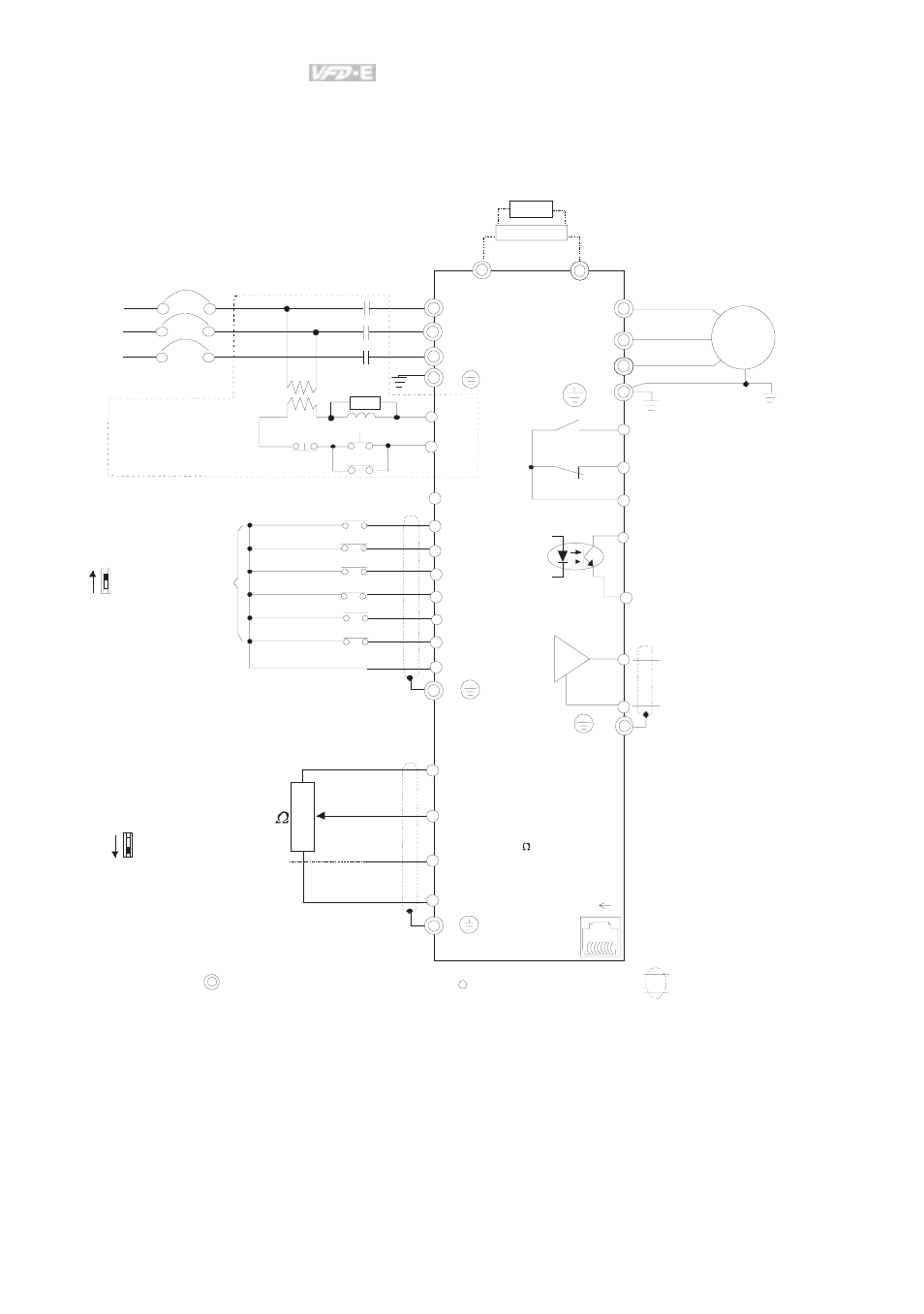
Figure 2 for models of VFD-E Series
VFD002E23A, VFD004E23A/43A, VFD007E23A/43A, VFD015E23A/43A, VFD002E23C,
VFD004E23C/43C, VFD007E23C/43C, VFD015E23C/43C, VFD002E23P, VFD004E23P/43P,
VFD007E23P/43P, VFD015E23P
AVI
ACI
ACM
+
+10V
5K
3
2
1
Power supply
+10V 20m A
Master Fr equency
0 to 10V 47K
Analog S ignal Common
E
Main c irc ui t (power) terminals
Contr ol c ircuit ter minals
Shielded l eads & Cable
E
R(L1)
S(L2)
F us e/NF B(No F use B reaker)
SA
OF F
ON
MC
MC
RB
RC
Recommended Circui t
when power s uppl y
is turned O FF by a
fault output
R(L1)
S(L2)
E
Analog Multi- func tion Output
Ter minal
factory setti ng: Analog fr eq.
/ c ur rent meter
0~1 0VDC/2 mA
U(T1)
V(T2)
W(T3)
IM
3~
AFM
ACM
RA
RB
RC
Motor
F ac tor y setting:
Driv e is in oper ation
48V50mA Max.
Multi-function
Photocoulper Output
Analog S ignal common
E
E
MO1
MCM
MI1
MI2
MI3
MI4
MI6
MI5
DCM
+24V
FWD/Stop
REV/Stop
Multi-s tep 1
Multi-s tep 2
Multi-s tep 3
Multi-s tep 4
Digital Si gnal Common
F ac tor y
setting
Sw2
AVI
ACI
Fact ory set ting:
ACI Mod e
ACI/AVI sw itch
Wh en switch ing to AVI,
it in dicates AVI2
-
8 1
Sw1
NPN
PNP
F act ory set tin g:
NPN Mo de
Please refer to F igur e 7
fo r w irin g of NPN
m od e an d PNP
m od e.
BUE
brake unit
( optional)
BR
brake resi stor
(opti onal)
Multi-function c ontact output
Refer to c hapter 2.4 for details .
Fac tor y setting is
malfunction indication
Fac tor y setting: output frequency
4-20mA/0-10V
T(L3)
T(L3)
RS-485 serial inter face
(NO T for VF D*E*C models)
1: Reserv ed
2: EV
5: SG +
6: Reserv ed
7: Reserv ed
8: Reserv ed
3: G ND
4: SG -
F or VFD*E*C models,
p lease ref er t o figu re 8.