Delta Electronics AC Motor Drive VFD-E User Manual
Page 116
Chapter 4 Parameters|
Revision June 2008, 04EE, SW--PW V1.11/CTL V2.11
4-63
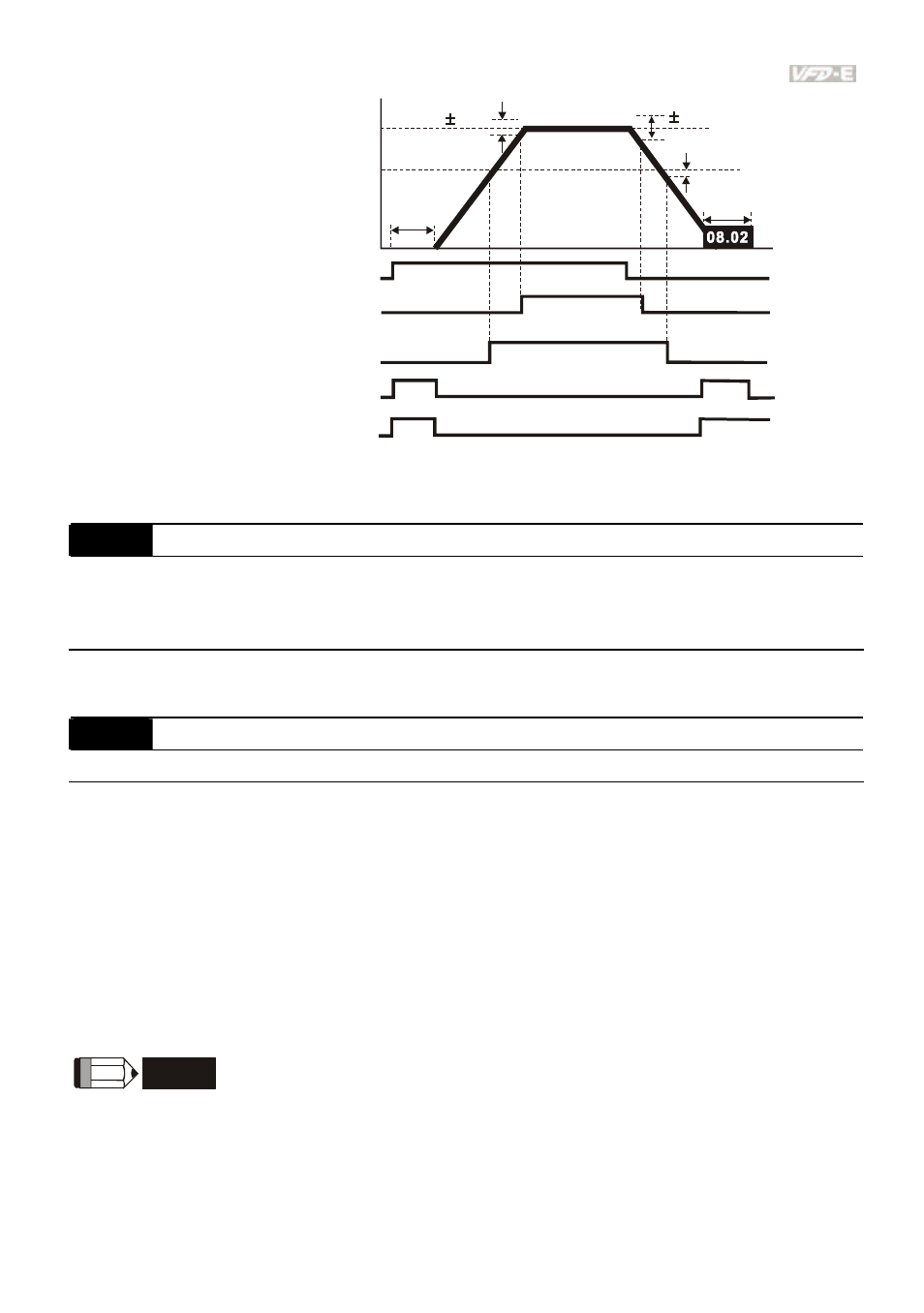
-2Hz
4Hz
2Hz
OFF
OFF
ON
ON
OFF
ON
OFF
ON
OFF
OFF
ON
OFF
ON
ON
detection
range
Frequency
master
frequency
desired
frequency
03.02/03.14
detection range
detection
range
DC braking tim
during stop
Time
waiting time
for
frequency
run/stop
setting 2
master freq. attained
(output signal)
setting 9/23
desired freq. attained
setting 03 zero speed indication
setting 19 zero speed indication
output timing chart of multiple function terminals
when setting to frequency attained or zero speed indication
03.03
Analog Output Signal (AFM)
Factory Setting: 0
Settings
0
Analog Frequency Meter (0 to Maximum Output Frequency)
1
Analog Current Meter (0 to 250% of rated AC motor drive current)
This parameter sets the function of the AFM output 0~+10VDC (ACM is common).
03.04
Analog Output Gain
Unit: 1
Settings
1 to 200%
Factory Setting: 100
This parameter sets the voltage range of the analog output signal AFM.
When Pr.03.03 is set to 0, the analog output voltage is directly proportional to the output
frequency of the AC motor drive. With Pr.03.04 set to 100%, the Maximum Output Frequency
(Pr.01.00) of the AC motor drive corresponds to +10VDC on the AFM output.
Similarly, if Pr.03.03 is set to 1, the analog output voltage is directly proportional to the output
current of the AC drive. With Pr.03.04 set to 100%, then 2.5 times the rated current
corresponds to +10VDC on the AFM output.
NOTE
Any type of voltmeter can be used. If the meter reads full scale at a voltage less than 10V, Pr.
03.04 should be set using the following formula:
Pr. 03.04 = ((meter full scale voltage)/10) x 100%