Delta Electronics AC Motor Drive VFD-E User Manual
Page 135
Chapter 4 Parameters|
4-82
Revision June 2008, 04EE, SW--PW V1.11/CTL V2.11
04.24
The Digital Input Used by PLC (NOT for VFD*E*C models)
Settings
Read Only
Factory setting: ##
Display
Bit0=1: MI1 used by PLC
Bit1=1: MI2 used by PLC
Bit2=1: MI3 used by PLC
Bit3=1: MI4 used by PLC
Bit4=1: MI5 used by PLC
Bit5=1: MI6 used by PLC
Bit6=1: MI7 used by PLC
Bit7=1: MI8 used by PLC
Bit8=1: MI9 used by PLC
Bit9=1: MI10 used by PLC
Bit10=1: MI11 used by PLC
Bit11=1: MI12 used by PLC
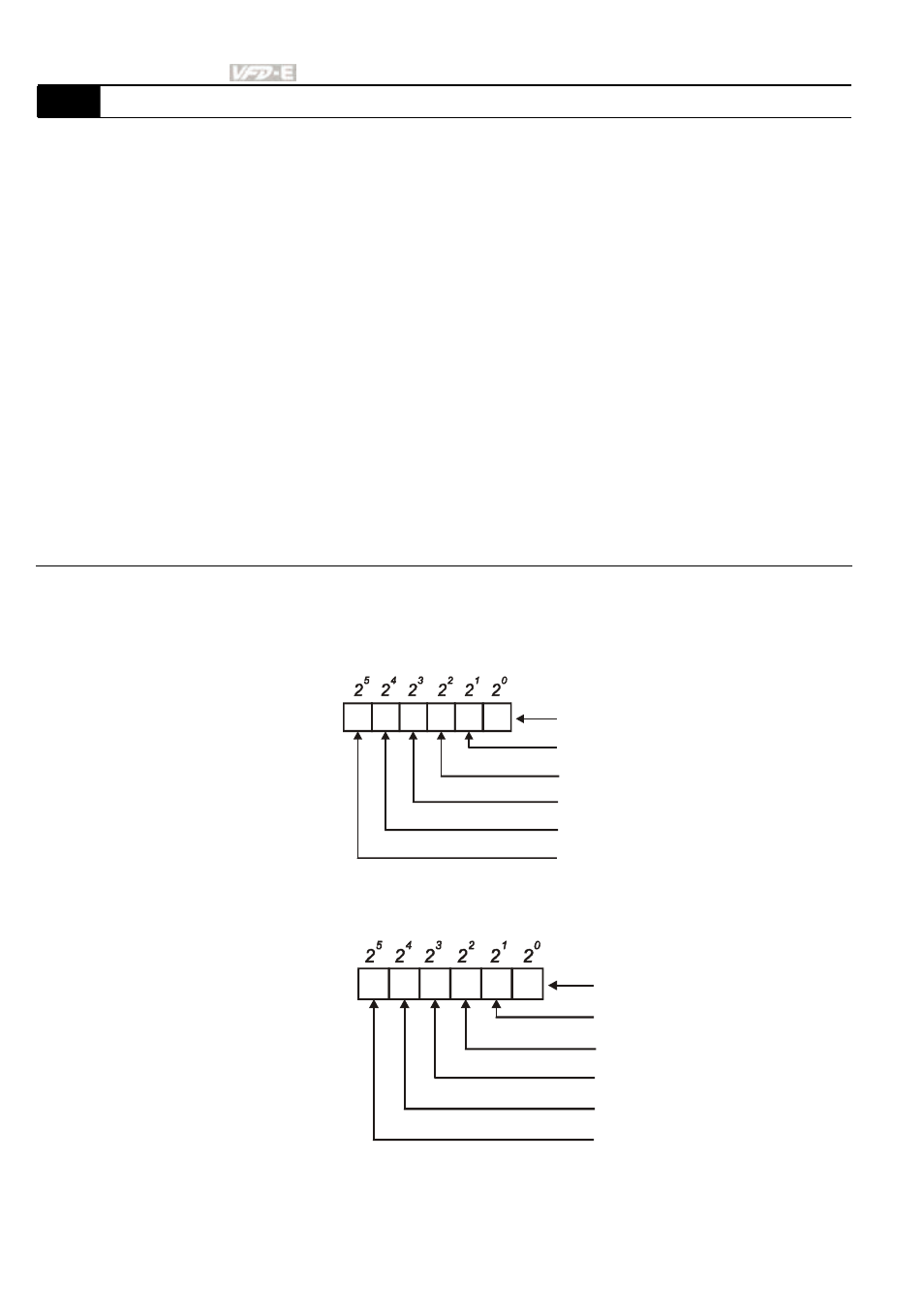
For standard AC motor drive (without extension card), the equivalent 6-bit is used to display
the status (used or not used) of each digital input. The value for Pr.04.24 to display is the
result after converting 6-bit binary into decimal value.
1
2
3
4
5
0
0=not used
1=used by PLC
MI1
MI2
MI3
MI4
MI5
MI6
Weights
Bit
For example: when Pr.04.24 is set to 52 (decimal) = 110100 (binary) that indicates MI3, MI5
and MI6 are used by PLC.
0
1
0
1
1
0
Weights
Bit
0=OFF
1=ON
MI1
MI2
MI3
MI4
MI5
MI6
- AC Motor Drive VFD-G (183 pages)
- SMT Power Inductor SIL104R (1 page)
- Q48SB (2 pages)
- Planar DC/DC Transformer ER/ER(Plate) 22 (1 page)
- SMT Power Inductor HCB1190B (1 page)
- Series E48SR (15 pages)
- E48SR12007 (15 pages)
- SMT Power Inductor SIWC1360 (1 page)
- PFC Chokes PFC2815V Series (1 page)
- SMT Power Inductor SIB86 (1 page)
- PMC-24V050W1AA (2 pages)
- SMT Power Inductor HCB1050 (1 page)
- SMT Power Inductor HAH1330 (1 page)
- PFC Chokes PFC4120V Series (1 page)
- PFC Choke PFC3520V Series (1 page)
- SMT Power Inductor HCB1047B (1 page)
- SMT Power Inductor HAH1365 (1 page)
- SMT Power Inductor HMS1355 (1 page)
- Series S48SA (13 pages)
- E48SC (2 pages)
- SMT Power Inductor SILM106 (1 page)
- Delphi Series L48DB (2 pages)
- S48SA (13 pages)
- E36SR (2 pages)
- 3KVA (31 pages)
- SMT Power Inductor HMU1056L (1 page)
- Through Hole Power Inductors THCBR1090 (1 page)
- SMT Power Inductor SIL625 (1 page)
- SMT Power Inductor 1378(S) (1 page)
- Through Hole Power Inductors 1411 (1 page)
- Current Sense Transformers TCE1310H (1 page)
- H48SR (13 pages)
- Series E48SH (15 pages)
- AC Motor Drive VFD-EL (209 pages)
- Through Hole Power Inductors THAH1095 (1 page)
- Suppression Inductors LFU09V (1 page)
- SMT Power Inductor HCB0740A (1 page)
- Power Output Module DVPPS01 (2 pages)
- SMT Power Inductor SIR74 (1 page)
- L36SA (2 pages)
- 4.5V~ 5.5V (3 pages)
- Delphi Series V48SB (2 pages)
- Series S48SP (14 pages)
- Series 240W (11 pages)
- Delphi Series E24SR (15 pages)