Delta Electronics AC Motor Drive VFD-E User Manual
Page 295
Appendix D How to Use PLC Function|
D-12
Revision June 2008, 04EE, SW--PW V1.11/CTL V2.11
The explanation of command order:
1 LD
X0
2 OR
M0
3 AND X1
4 LD
X3
AND M1
ORB
5 LD
Y1
AND X4
6 LD
T0
AND M3
ORB
7 ANB
8 OUT Y1
TMR
T0 K10
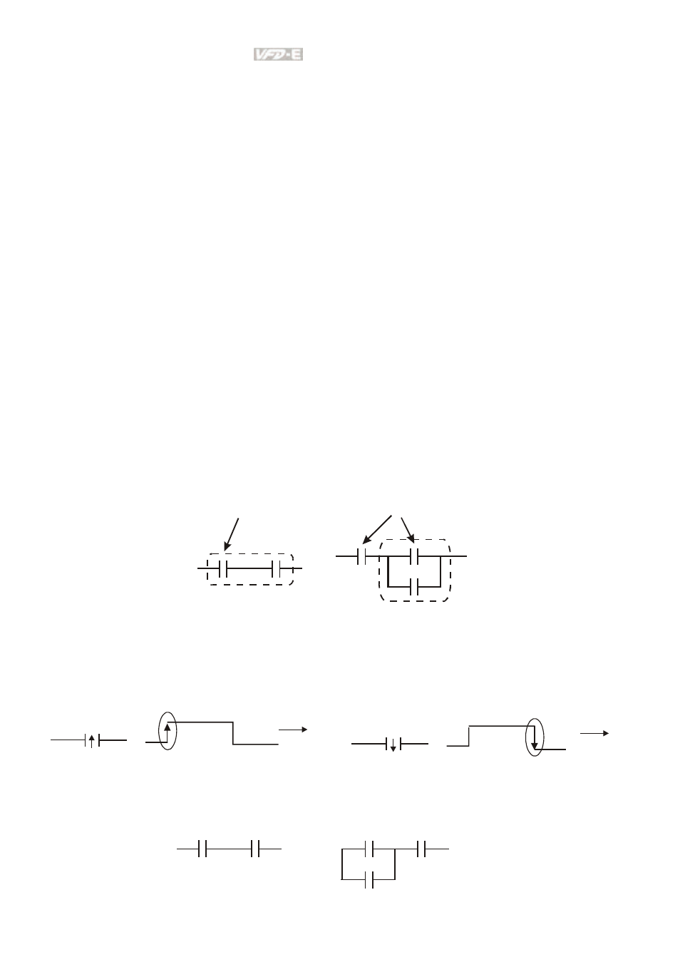
The detail explanation of basic structure of ladder diagram
1.
LD (LDI) command: give the command LD or LDI in the start of a block.
AND Block
OR Block
LD command
LD command
The structures of command LDP and LDF are similar to the command LD. The difference is
that command LDP and LDF will act in the rising-edge or falling-edge when contact is ON as
shown in the following.
X0
OFF
ON
OFF
Time
Falling-edge
X0
OFF
ON
OFF
Time
Rising-edge
2.
AND (ANI) command: single device connects to a device or a block in series.
AND command
AND command
- AC Motor Drive VFD-G (183 pages)
- SMT Power Inductor SIL104R (1 page)
- Q48SB (2 pages)
- Planar DC/DC Transformer ER/ER(Plate) 22 (1 page)
- SMT Power Inductor HCB1190B (1 page)
- Series E48SR (15 pages)
- E48SR12007 (15 pages)
- SMT Power Inductor SIWC1360 (1 page)
- PFC Chokes PFC2815V Series (1 page)
- SMT Power Inductor SIB86 (1 page)
- PMC-24V050W1AA (2 pages)
- SMT Power Inductor HCB1050 (1 page)
- SMT Power Inductor HAH1330 (1 page)
- PFC Chokes PFC4120V Series (1 page)
- PFC Choke PFC3520V Series (1 page)
- SMT Power Inductor HCB1047B (1 page)
- SMT Power Inductor HAH1365 (1 page)
- SMT Power Inductor HMS1355 (1 page)
- Series S48SA (13 pages)
- E48SC (2 pages)
- SMT Power Inductor SILM106 (1 page)
- Delphi Series L48DB (2 pages)
- S48SA (13 pages)
- E36SR (2 pages)
- 3KVA (31 pages)
- SMT Power Inductor HMU1056L (1 page)
- Through Hole Power Inductors THCBR1090 (1 page)
- SMT Power Inductor SIL625 (1 page)
- SMT Power Inductor 1378(S) (1 page)
- Through Hole Power Inductors 1411 (1 page)
- Current Sense Transformers TCE1310H (1 page)
- H48SR (13 pages)
- Series E48SH (15 pages)
- AC Motor Drive VFD-EL (209 pages)
- Through Hole Power Inductors THAH1095 (1 page)
- Suppression Inductors LFU09V (1 page)
- SMT Power Inductor HCB0740A (1 page)
- Power Output Module DVPPS01 (2 pages)
- SMT Power Inductor SIR74 (1 page)
- L36SA (2 pages)
- 4.5V~ 5.5V (3 pages)
- Delphi Series V48SB (2 pages)
- Series S48SP (14 pages)
- Series 240W (11 pages)
- Delphi Series E24SR (15 pages)