Delta Electronics AC Motor Drive VFD-E User Manual
Page 121
Chapter 4 Parameters|
4-68
Revision June 2008, 04EE, SW--PW V1.11/CTL V2.11
Bit6: MO6/RA6 Status
Bit7: MO7/RA7 Status
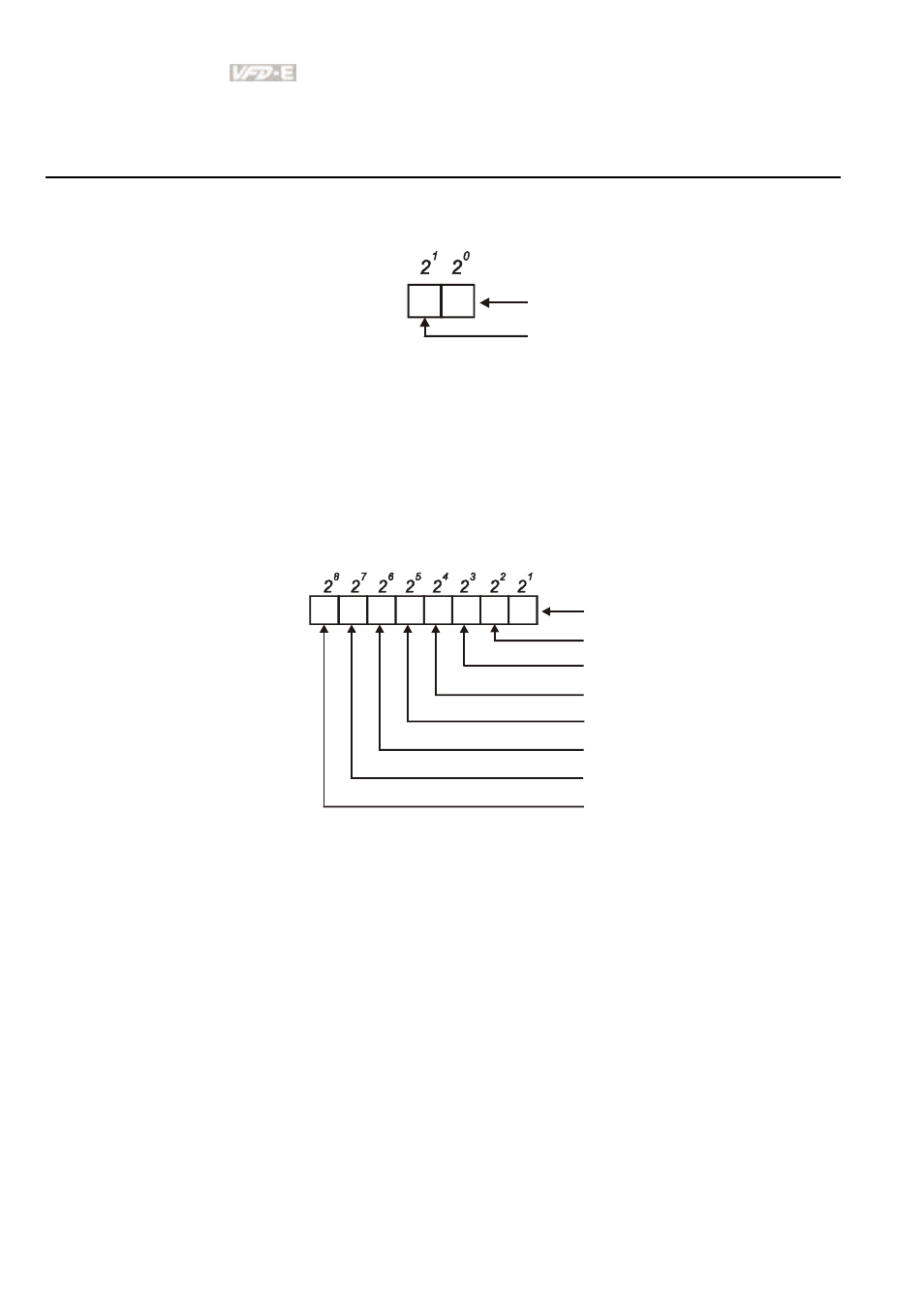
For standard AC motor drive (without extension card), the multi-function output terminals are
falling-edge triggered and Pr.03.13 will display 3 (11) for no action.
1 0
Weights
Bit
0=Active
1=Off
Relay 1
MO1
For
Example:
If Pr.03.13 displays 2, it means Relay 1 is active.
The display value 2 =bit 1 X 2
1
When extension card is installed, the number of the multi-function output terminals will
increase according to the extension card. The maximum number of the multi-function output
terminals is shown as follows.
1 0
Weights
Bit
Relay 1
MO1
3
2
5 4
7 6
MO2/RA2
MO3/RA3
MO4/RA4
MO5/RA5
MO6/RA6
MO7/RA7
0=Active
1=Off
See also other documents in the category Delta Electronics Tools:
- AC Motor Drive VFD-G (183 pages)
- SMT Power Inductor SIL104R (1 page)
- Q48SB (2 pages)
- Planar DC/DC Transformer ER/ER(Plate) 22 (1 page)
- SMT Power Inductor HCB1190B (1 page)
- Series E48SR (15 pages)
- E48SR12007 (15 pages)
- SMT Power Inductor SIWC1360 (1 page)
- PFC Chokes PFC2815V Series (1 page)
- SMT Power Inductor SIB86 (1 page)
- PMC-24V050W1AA (2 pages)
- SMT Power Inductor HCB1050 (1 page)
- SMT Power Inductor HAH1330 (1 page)
- PFC Chokes PFC4120V Series (1 page)
- PFC Choke PFC3520V Series (1 page)
- SMT Power Inductor HCB1047B (1 page)
- SMT Power Inductor HAH1365 (1 page)
- SMT Power Inductor HMS1355 (1 page)
- Series S48SA (13 pages)
- E48SC (2 pages)
- SMT Power Inductor SILM106 (1 page)
- Delphi Series L48DB (2 pages)
- S48SA (13 pages)
- E36SR (2 pages)
- 3KVA (31 pages)
- SMT Power Inductor HMU1056L (1 page)
- Through Hole Power Inductors THCBR1090 (1 page)
- SMT Power Inductor SIL625 (1 page)
- SMT Power Inductor 1378(S) (1 page)
- Through Hole Power Inductors 1411 (1 page)
- Current Sense Transformers TCE1310H (1 page)
- H48SR (13 pages)
- Series E48SH (15 pages)
- AC Motor Drive VFD-EL (209 pages)
- Through Hole Power Inductors THAH1095 (1 page)
- Suppression Inductors LFU09V (1 page)
- SMT Power Inductor HCB0740A (1 page)
- Power Output Module DVPPS01 (2 pages)
- SMT Power Inductor SIR74 (1 page)
- L36SA (2 pages)
- 4.5V~ 5.5V (3 pages)
- Delphi Series V48SB (2 pages)
- Series S48SP (14 pages)
- Series 240W (11 pages)
- Delphi Series E24SR (15 pages)