Toa SX-2000 Series Installation User Manual
Page 9
9
Setting Software. (See the separate Setting
Software Instructions, "Pattern Settings.")
25. 24v DC Output Terminals [DC OUT]
these terminals can provide up to 100 mA of 24 V
Dc power to connected external equipment.
26. Data Input Terminals [ACK/RES/LAMp]
Photo coupler inputs. A current of approximately
2 mA flows when shorted, and the voltage
becomes approximately 24 V Dc when opened.
• ACK
the buzzer may sound when a failure is detected
in the SX-2000Sm.
Short the AcK terminals to stop the buzzer.
If a failure occurs while AcK is on, it is
automatically received.
these terminals serve the same function as the
front-mounted fAult AcK key (10).
• RES
In accordance with the DIP switch 4 (19) setting,
shorting these terminals resets once the failure
information (the buzzer and fault indicators) of
the SX-2000Sm.
these terminals serve the same function as the
front-mounted fAult rESEt key (11).
• LAMp
used to test the indicators on the SX-2000Sm's
front panel. All moDE and fAult indicators (4)
– (9) remain lit and the buzzer sounds as long as
these terminals are set to oN.
27. Control Input Terminals [INpUT C1 – C8]
Photo coupler inputs. A current of approximately 2
mA flows when shorted, and the voltage becomes
approximately 24 V Dc when opened. functions
can be assigned to these terminals using the SX-
2000 Setting Software. (See the separate Setting
Software Instructions, "Event Settings.")
28. Analog Link Output Terminals
[ANALOg LINK OUT 1/2]
connect these terminals to the analog link input
terminals of the SX-2000AI, SX-2100AI, SX-
2000Ao, or SX-2100Ao.
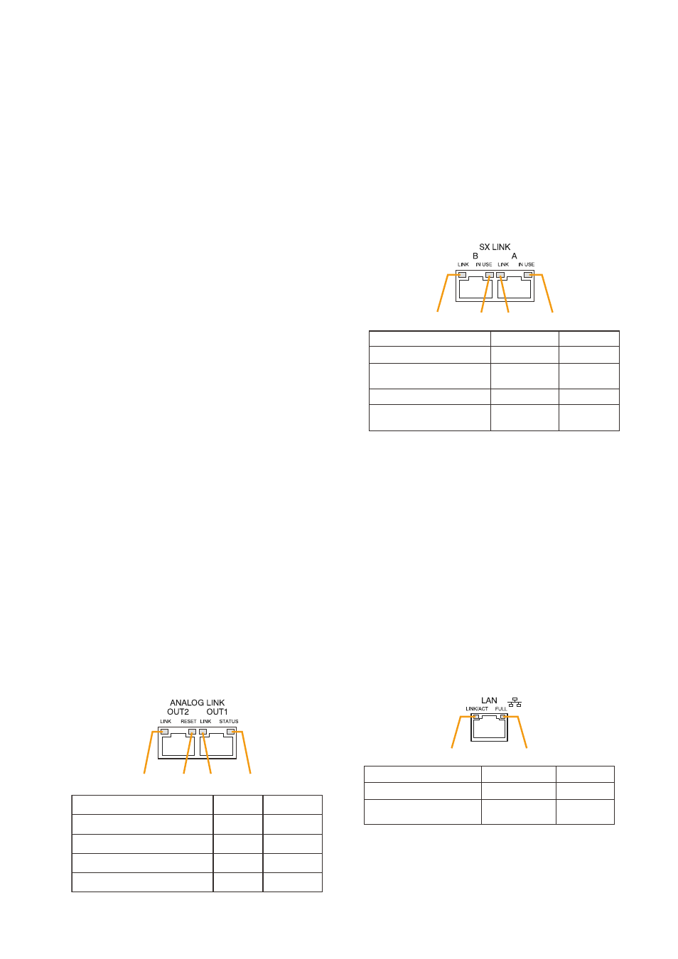
29. SX Link Terminals [SX LINK A/B]
use switching hubs to connect between the SX
link terminals of the SX-2000Sm, SX-2000AI, SX-
2100AI, SX-2000Ao, and SX-2100Ao.
connect each of the SX links A and B to the same
switching hub*, or to different switching hubs* that
have been connected in star configuration.
Notes
• Be sure to connect both terminals of A and B.
• After connection completion, press the Reset
key to reactivate the SX-2000Sm.
* contact your toA dealer for more information
on switching hubs.
30. MAC Address for SX Link Connections
mAc address to be used for SX link connection.
31. LAN Connection Terminal [LAN]
used when setting times to be recorded in
operation logs.
connect this terminal to a switching hub that
supports the 10BASE-t or 100BASE-tX standard.
Since time settings can also be performed via a
Pc, connect the Pc to the switching hub as well.
Notes
• Do not connect the switching hub to the LAN.
• Avoid directly connecting the SX-2000SM to the
Pc via a cross cable.
(See the separate Setting Software Instructions
"Basic Settings" for settings related to the SX-
2000Sm's IP address, etc.)
31. MAC Address for LAN Connection
A 12-digit hexadecimal address number peculiar
to and assigned to the network-connected unit.
1
2
3
4
Function
LED On/Flashing
LED Off
1. B connection confirmation
2. B operation in progress
indication
3. A connection confirmation
4. A operation in progress
indication
Connected
Operating
Connected
Operating
Unconnected
Not operating
Unconnected
Not operating
1
2
Function
LED On/Flashing
LED Off
1. Connection confirmation
2. Full duplex
communication detection
Connected
Detected
Unconnected
Undetected
SX-2000SM
1
2
3
4
Function
LED On
LED Off
1. OUT 2 connection confirmation
2. OUT RESET output
3. OUT 1 connection confirmation
4. OUT STANDBY start output
Connected
Resetting
Connected
Start
Unconnected
Normal
Unconnected
Normal