Toa SX-2000 Series Installation User Manual
Page 61
61
(OPTION)
ATTENTION
CUT SJP181 AND SJP182
WHEN MOUNTING
TRANS. T10
8
T108
SJP181
(OPTION)
ATTENTION
CUT SJP161 AND SJP162
WHEN MOUNTING
TRANS. T10
6
T106
(OPTION)
ATTENTION
CUT SJP121 AND SJP12
2
WHEN MOUNTING
TRANS. T10
2
T102
SJP122
SJP121
SJP172
(OPTION)
ATTENTION
CUT SJP171 AND SJP17
2
WHEN MOUNTING
TRANS. T10
7
T107
SJP171
(OPTION)
ATTENTION
CUT SJP141 AND SJP14
2
WHEN MOUNTING
TRANS. T10
4
T104
SJP141
SJP152
SJP162
(OPTION)
ATTENTION
CUT SJP151 AND SJP15
2
WHEN MOUNTING
TRANS. T10
5
T105
SJP142
SJP151
SJP182
SJP161
(OPTION)
ATTENTION
CUT SJP111 AND SJP11
2
WHEN MOUNTING
TRANS. T101
T101
SJP112
SJP111
SJP132
(OPTION)
ATTENTIO
N
CUT SJP131 AND SJP132
WHEN MOUNTING
TRANS. T103
T103
SJP131
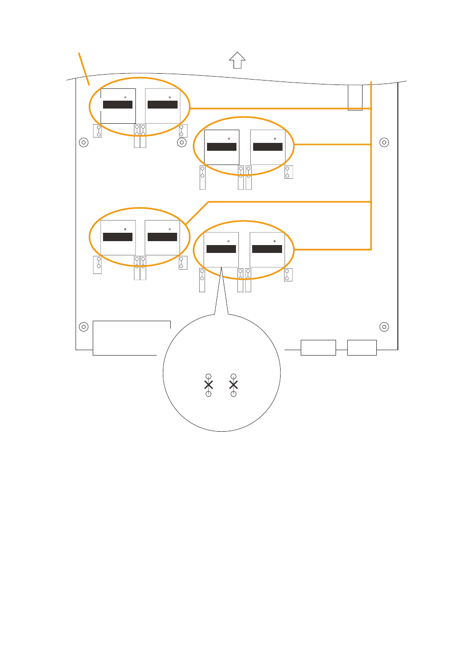
SX-2000AO link circuit board
Front panel side
IT-450 mounting position
4
5
SJP112
SJP111
Example of how to cut jumpers
when a transformer is installed
in the place of Output 1 (T101).
OUTPUT 8
OUTPUT 6
OUTPUT 2
OUTPUT 7
OUTPUT 1
OUTPUT 3
OUTPUT 4
OUTPUT 5
Step 4. Install the It-450 transformer in the designated transformer installation place for outputs 1 – 8, then
solder it in place.
output 1: t101; output 2: t102; output 3: t103; output 4: t104; output 5: t105; output 6: t106; output 7:
t107; output 8: t108
Step 5. cut the jumper wires on both sides of the installed transformer.
Note
take care to ensure that no fragments of the cut jumpers contact the transformer case.
Step 6. replace the link circuit board and top panel.
Notes
• Note the specific shapes of the different screws when replacing the link circuit board and top panel.
(See Steps 1 and 3.)
• When connecting the flat cable to the link circuit board, handle the connector with care. (See Step 2.)