Input equipment connections – Toa SX-2000 Series Installation User Manual
Page 103
103
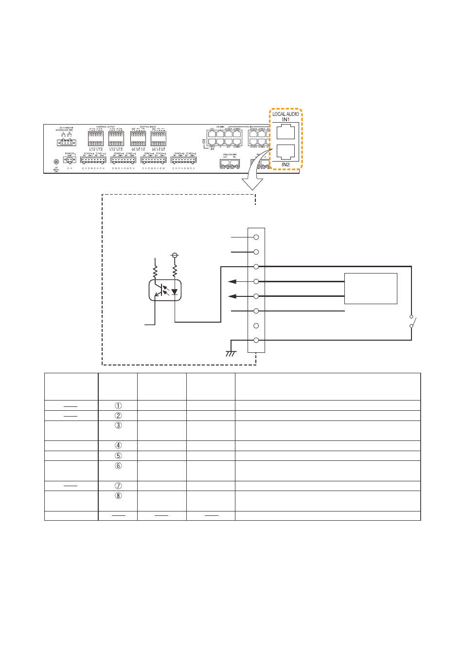
4.2. Input Equipment Connections
4.2.1. Connections of SX-2100AO's Local audio control input terminals
use StP category 5 straight cables for connections.
the diagram below shows cable connections to the local audio control input terminal.
Photo coupler
VCC
4.4 kΩ
SX-2100AO
SX-2100AO
Internal circuit
Control input
Local audio control input terminals
(RJ45)
Local audio control input terminals
Audio input (H)
Audio input (C)
External power source
1
2
3
4
5
6
7
8
Sound source
Control IN
Audio input (H)
Audio input (C)
External power
source
GND
SHIELD
Orange/White
Orange
Green/White
Blue
Blue/White
Green
Brown/White
Brown
Green/White
Green
Orange/White
Blue
Blue/White
Orange
Brown/White
Brown
Not used
Not used
Connect to the external device's control output terminal*
1
(positive polarity).
Connect to the external device's audio signal*
2
(hot).
Connect to the external device's audio signal*
2
(common).
Power input terminal from external power supply for
control input *
3
Not used
Connect to the external device's control output terminal
(negative polarity).
Connect to the external device's audio signal ground*
2
.
Signal Type
RJ45
connector
pin No.
Cable color
(T568B type)
Cable color
(T568A type)
Remarks
*
1
Specifications of the control input are as follows.
2 inputs, no-voltage make contact input, open voltage: 12 V Dc, short-circuit current: 2 mA, photo cuppler
input
*
2
Specifications of the audio input are as follows.
0 dB, 10 kΩ, electrically-balanced input
Do not connect a microphone having no preamplifier directly to the SX-2100Ao. to enable the connection,
use a preamplifier between the microphone and SX-2100Ao.
*
3
refer to
for isolating the control input by using external power supply.
Note
for the wiring when a change is made to use
an external power supply, refer to
.